 Facebook
 Google
 GitHub
 Linkedin
Adding Robots to CNC Machines: What You Need to Know
Robots can greatly increase machine uptime in a manufacturing shop, but unless a few prerequisites are met, that machine time might just generate more scrap than sales.
A Universal Robots UR10e is a common choice for loading CNC machines, and it can repeat its position to within ±0.05 mm. A precision-machined part often has to land within ±0.025 mm. That gap between the robot manufacturers’ promised specs vs. the drawing demands is the center of a decision that more manufacturers face as skilled labor becomes more scarce: automate the CNC floor, or send the precision work out. The solution depends heavily on an understanding of tolerance and how it applies to the situation.
The CNC precision machining tolerances that separate precision work from standard work start at around ±0.025 mm (±0.001 in), roughly IT8 to IT9 on a 30 to 50 mm feature. In that band, a robot cell can deliver nights and weekends of extra spindle time, or a full tray of scrap, depending on how well the process around it is engineered.
Robots certainly are a right answer for plenty of CNC tasks. The useful questions include what work is most appropriate, what the cell really costs, and what it takes to hold tolerance when nobody is watching.
Why Manufacturers Are Adding Robots to CNC Machines
Deloitte and The Manufacturing Institute estimate that US manufacturers need around 3.8 million workers between 2024 and 2033, and that roughly 1.9 million of those roles could go unfilled. A CNC machine that waits for someone to load it is expensive capacity sitting idle, and the current demand for robots reflects that pressure.
North American companies ordered 36,766 robots in 2025, up 6.6% from 2024, according to A3, and collaborative robots made up 19.6% of those orders. Machine tending is a natural job for these robots. Opening a door, swapping a finished part for a blank, and pressing cycle start are all very simple, repetitive jobs that keep skilled people away from programming, setup, and problem-solving.
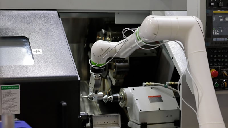
Figure 1. Robots are well suited to tending CNC machines. Image used courtesy of Adobe Stock
Robot Automation: A Matter of Precision and Tolerances
Robot Repeatability Against the Tolerance Band
The previously stated robot specs come straight from the manufacturer. The UR10e's ±0.05 mm is stated on its ISO 9283 datasheet, while FANUC, another industry leader, lists ±0.03 to ±0.05 mm across its CRX range. A part toleranced at ±0.025 mm has 0.05 mm to play with in total. Left to itself, the robot could use up the whole tolerance before the spindle even starts.
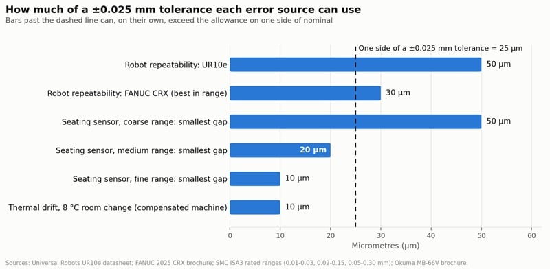
Figure 2. Comparing introduced tolerance errors against a 0.025 mm standard. Image used courtesy of Haizol
Good integrators design around this, so the robot never does the actual precision work. The robot only drops the blank roughly into place, where a self-centering vise, chuck stops, or three-point nest seats the blank onto its datums as they clamp.
Because tending positions are taught with the robot standing in the real cell, its absolute accuracy, which ISO 9283 measures separately from repeatability, barely enters the picture. The risk arrives later. A replaced gripper finger, a knock during a jam, or an axis re-mastered after service all affect every taught point at once, so load positions need re-checking after any robot maintenance.
Seating Checks and Thermal Drift
The bigger change is in how errors behave. With an operator present, a chip that finds its way under a clamped part produces one bad part that immediately gets flagged. Without an operator, the same fault repeats on every cycle until something stops the machine. A 6-minute cycle over a 10-hour night is 100 parts, so a chip that lifts the datum on part five can leave the morning shift with 95 copies of the same mistake.
To prevent this seating-gap error, products like SMC's ISA3 air-gap sensor can be found in versions rated for gaps of 0.01 to 0.03 mm, 0.02 to 0.15 mm and 0.05 to 0.30 mm. Choose the wrong combo, like a coarse sensor version applied to a ±0.025 mm part, and a chip thick enough to scrap it can sit underneath while the light stays green. A seating sensor must be able to detect a gap smaller than the tolerance it protects.
Heat adds a slower kind of drift. A 2017 review in the Chinese Journal of Mechanical Engineering (Zhou et al.) puts thermal deformation at about 40 to 70% of total machining error in precision manufacturing. Even Okuma's MB-66V, a machine marketed on thermal stability, reports 10 µm of change for an 8°C swing in room temperature with its compensation switched on. On a ±0.025 mm part, that is 40% of the allowance on one side of nominal.
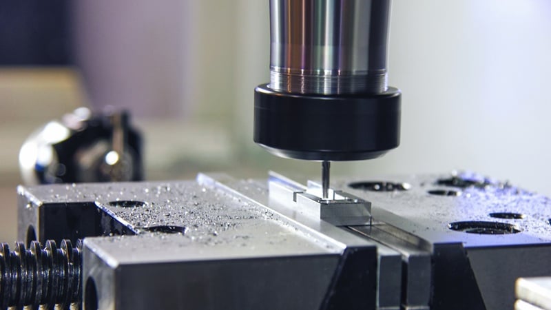
Figure 3. A small chip nestled under the clamped part can create scrap if not caught in time. Image used courtesy of Adobe Stock
Requirements for Unattended Running
These errors all point to the first requirement for lights-out machining: a process must already run smoothly with an operator present. Unattended running makes a capable process more productive, but similarly, it also makes an unstable process fail faster. A shop should know how many hours and parts a job holds tolerance under supervision before trusting it to the night shift.
Automating the Checks
From there, every informal check the operator used to make needs a replacement. Probing confirms that a part sits flat and updates work offsets before cutting. Tool-life limits and sister tools handle wear, and broken-tool detection catches sudden failures. Tool manufacturer Marposs claims that its TBD laser detector checks tool integrity in under one second on supported tools. Coolant level, air pressure, and chip-bin status belong on the alarm list too, because a machine that runs dry will keep cycling and reliably producing more scrap.
Restarts
Okuma's MB-66V brochure singles out machine startup and the resumption of machining as the two moments when thermal stability matters most. Robot cells tend to create more of those moments than attended machines do. A missed grip, a full chip bin, or a tripped door interlock might stop the cell and the machine cools down until someone comes in to initiate the fix. A proper restart routine includes three vital steps of warming the spindle, probing a reference feature, and flagging the first parts for inspection. This startup costs far less than the scrap it prevents. ISO 230-3 gives the test methods for measuring how long a specific machine takes to settle.
Verfication
Someone also has to verify the night's work. A cell that runs until morning can make parts faster than a day-shift quality team can measure them, so some inspection has to move into the cycle. Marposs describes on-machine probing systems that run CMM-style checks without unclamping the part. Add a serial number or laser mark linked to each part's machine, time, tool counts, and probe results, and a bad night shrinks to a handful of quarantined parts while the rest of the batch ships.
Fix the Process, Then Choose Who Machines the Part
The precision in a robot cell has to come from the fixture, the measurement tools, and the thermal state of the machine. A shop that has those under control can let a cell run through the night and have better faith in what it finds in the morning. A shop still working on these problems is mostly just automating its scrap production.
First, make the process capable–and prove it with data. Then sort the parts: repeatable work in the looser tolerance bands goes into the cell, and the tightest, most variable work goes to whoever is best equipped to make it, in-house or outside. The robot will repeat whatever it is given, so be sure that you make the right decision on what processes it’s assigned to handle.