Facebook
 Google
 GitHub
 Linkedin
Mitsubishi PLCs: Complex Sequences with Step and Return Logic
Learn how to segment your sequential control logic for easy troubleshooting using Step (STL) and Return (RET) commands in Mitsubishi PLCs.
In large automated systems that feature a large number of tasks in repetitive routines, the complexity of ladder logic can affect the troubleshooting process. We need to try and identify ways to optimize ladder logic programming to make it simple, while being capable of handling complex tasks.
Traditional ladder logic programming methods still form an integral part of most sequential controls, the use of programming functions like step ladder (STL) and return (RET) instructions, which are featured in Mitsubishi PLCs, can prove effective for the modular, segmented, and easy-to-troubleshoot program. This article examines the use of step and return functions in relation to traditional programming methods through a practical example project involving Mitsubishi FX3U PLC.
Implementing the Sequential Control Logic
For this tutorial, let's consider a simple automation project that features a conveyor system, sensors, and a pneumatic cylinder that acts as a pusher. In this project, we are going to compare the sequential control aspect using traditional logic and the use of Step and Return functions.
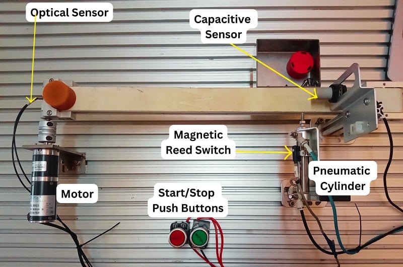
Figure 1. Sample project to demonstrate the use of Step and Return functions.
Before looking at how to implement the sequential logic for the sample project, consider understanding the sequence of operations. In the case of the project example in Figure 1, the operation sequence is as follows:
- The start push button (green) is pressed to start the process.
- The conveyor starts running once an item is detected by the optical sensor.
- The conveyor stops once the capacitive sensor detects the item at the conveyor's endpoint.
- A pneumatic piston pushes the item to a collection bin and retracts.
- The system returns to step 2, ready for the next item.
For our PLC connection, we are going to use the FX3U Mitsubishi PLC, and below is the I/O table representing the addresses of each input and output device.
|
|
Address | Description |
| Digital inputs | X000 | Start push-button (green) |
| X001 | Stop push-button (red) | |
| X002 | Optical sensor | |
| X003 | Capacitive sensor | |
| X004 | Magnetic reed switch | |
| Digital outputs | Y000 | Conveyor belt motor |
| Y001 | Pneumatic cylinder; single solenoid valve. | |
| Timer | T0 | Delays before the pneumatic cylinder retracts. |
Table 1. I/O table for showing addresses and their description
Traditional Ladder Logic Implementation
This involves the use of latched ladder logic programs that progressively grow complex as the sequence grows, especially in large automation systems. For this example project, when the start push button is pressed, a digital input signal is sent to X000 in the PLC's input and triggers an internal relay M0. The internal relay’s state remains ON even after the push button is released, and when the stop push button is pressed, the latched output M0 is reset, and its state changes to OFF. The internal relay can then be used to start the second process in the ladder logic sequence.
In the second sequence, the ‘ON’ state of the internal relay M0 and the state of the optical sensor, connected to X002, after detecting an item at the conveyor start point is used to trigger the motor output (Y000) driving the conveyor belt. The capacitive sensor at the end of the conveyor connected to X003 is represented as a normally closed contact to cancel the latched conveyor motor output once triggered.
In the final sequence, the capacitive sensor triggers the extension of the pusher once the item is detected and delays for 5 milliseconds before canceling the latched output to the 5/2 single solenoid directional control valve, which is used to trigger the pneumatic cylinder. This retraction delay is triggered using an input signal from the magnetic reed switch featured on the pneumatic cylinder and connected to address X004.

Figure 2. Traditional ladder logic example to implement sequential control for the conveyor system sample project.
Step and Return Function Implementation
The sequential logic implementation of the project using Mitsubishi’s STL and RET instructions involves the segmentation of the sequences and the creation of transition orders in which the logic is to be executed.
In a sequential control program, STL instructions define the beginning of a step and are always paired with a state register (S) in the syntax: -[STL Sn]-, where ‘n’ is the address of a state register or, more simply, the step number. During the PLC scan cycle, only the active step or steps within the STL block are executed, while the inactive ones are skipped. This ensures that scan times are reduced and sequences are handled separately.
To initialize an STL function, you first need to set the state register via an input state within the logic. For instance, X000 can be used to -[SET S0]-.
RET, or return instruction, prepares the logic for the next complete cycle of sequences and is always placed after the logic of the final STL instruction. This function is useful in creating boundaries to where the sequence control ends, and in a step ladder logic, the PLC may exhibit unpredictable behavior and even flag an error.
Step 1 (S0)
Going back to the STL/RET sequential logic implementation for the sample conveyor project, the sequences were divided into two steps (S0 and S1). When the start push button X000 is pressed, the latched S0 goes on, and when initialized by -[STL S0]-, the sequence begins.
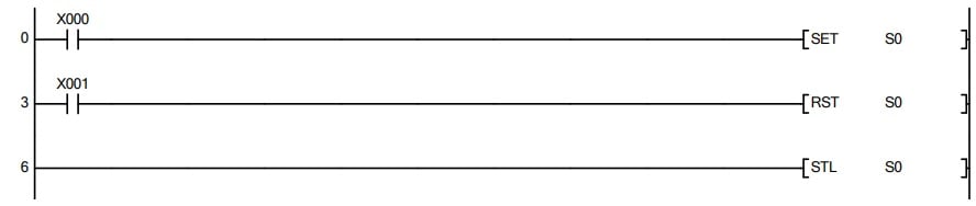
Figure 3. The first section of the sequential logic shows the activation of step 0.
The step will likewise be reset immediately if the stop push button X001 is pressed.
Step 2 (S1)
When the optical sensor (X002) detects an item, the conveyor motor (Y000) activates and is stopped by the item detection with the capacitive sensor (X003). This capacitive sensor is used to trigger the next step, S1.
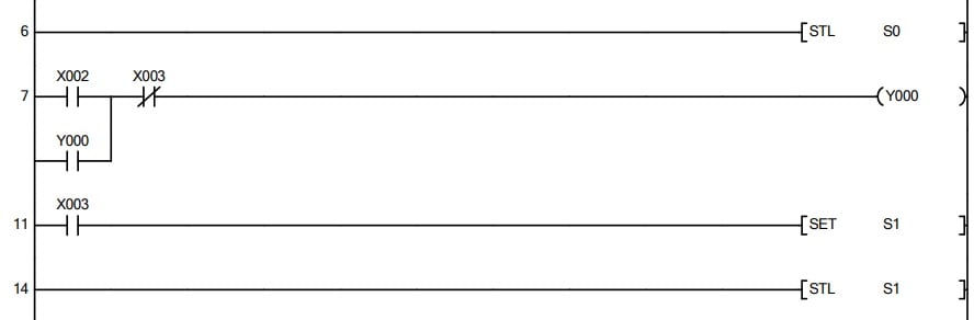
Figure 4. Continuation of the sequential logic illustrating the conveyor motion until the item is detected by the capacitive sensor (X003), setting the next step, S1. Image used courtesy of the author
Note that from Figure 4 above, when the next step in the sequence is activated, the previous step, in this case, S0, is automatically deactivated. This can cause challenges if the sequence is the last in the logic and might prompt the need for adding a timer (or event) to cancel and reset the last step, S1, as seen in Figure 5. In some cases, if you intend to loop a repetitive task, a normally closed contact of the last step can be added in series with the condition that activates the first step. In this project, however, when the pneumatic cylinder extends to push the object, the magnetic reed switch (X004) is triggered, which starts a time count to reset this final step. RET is added immediately after the logic within this last step.
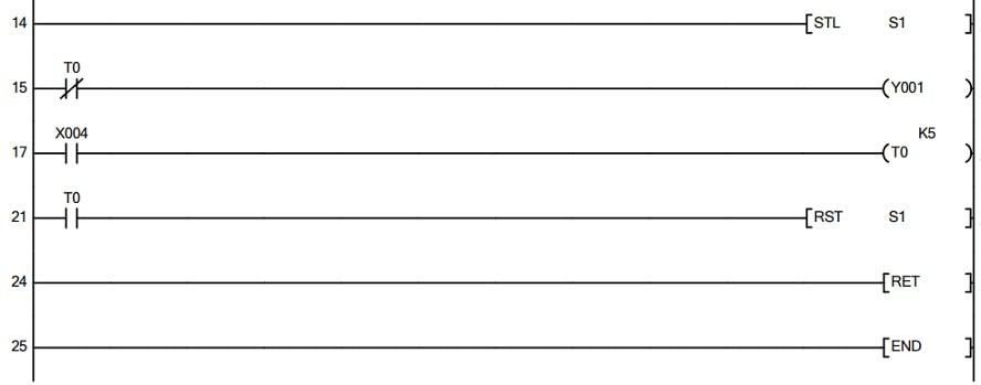
Figure 5. The final sequential logic handles the extension and retraction of the pneumatic pusher and features RET instruction.
When Step/Return is a Life Saver
From my own experience with a range of automation projects, STL/RET instructions are worth using when the complexity of the sequential control is key. This is because, with this method, visualizing and managing longer sequential logic is simplified, making error handling and troubleshooting simpler, as an affected step can be directly isolated and modified without affecting the entire logic.
However, for very basic sequential control, the use of STL might be unnecessary as the traditional approach can prove direct. Another note is that while the steps feature segmentation for clarity, the actual logic within the steps might still follow standard ladder logic implementation. As a programmer or a maintenance technician, you can benefit from knowing how to use STL/RET instruction in Mitsubishi PLCs for both initial development and long-term maintenance.
All images used courtesy of the author