Tutorial: Analog Signals with Phoenix Contact’s PLCnext Platform
Learn how to connect analog inputs, either voltage or current, to the Phoenix Contact’s IIoT PLC platform and design simple data processing programs with the PLCnext Engineer IDE.
Before you get started, be sure to check out our recent introduction to discrete I/O with the PLCnext platform.
Analog signals from sensors allow engineers to monitor the health of a system over time, rather than being limited to simple on/off boundaries provided by discrete switching devices.
In this tutorial, we will connect an analog sensor to the PLCnext, an IIoT platform from Phoenix Contact that combines the functionality of a PLC with the expandability of an industrial operating system to leverage data storage, visualization, and processing capabilities common in more complex IPCs.
For this project, we are still only making use of the PLC component of the controller, but acquiring data and controlling the field devices is the first step before we move on to more advanced data analytic applications, so we’ll handle the controller one piece at a time.
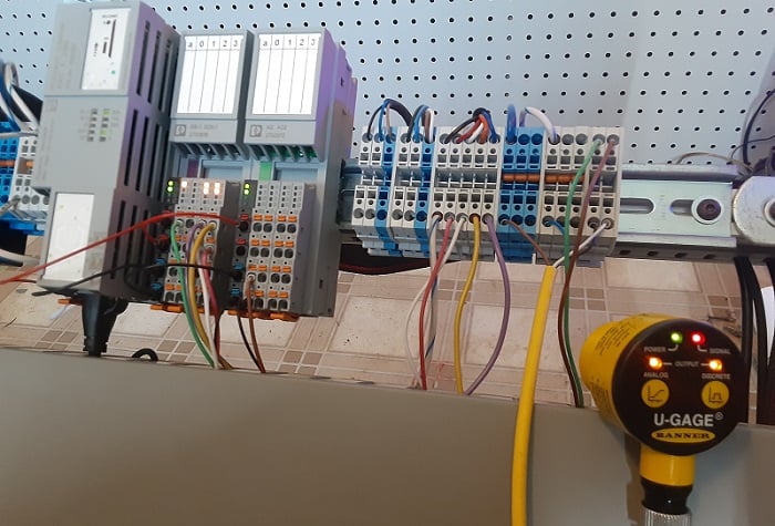
Figure 1. The bench setup for the project uses an analog sensor and a stack light (off the right side of the picture). Image used courtesy of the author
Required PLCnext Hardware
For this project, any analog input device will work, but I have chosen an ultrasonic distance sensor that emits both a 4-20 mA analog and a PNP switching output. This way, I can effectively work with both analog and discrete measurements using a single sensor. Another common device for testing analog (voltage) signals is a potentiometer.
The PLCnext includes several options for analog inputs, but the module specific to this bench test setup is the 2702072, a combination 2x analog in / 2x analog out. The module can handle voltage and current, both in a variety of common industrial ranges, so we can easily make use of either voltage or current emitting sensor signals.
In my project, I have also included a 4-tier stack light. The lowest tier will illuminate when the PNP switching output energizes. The remaining 3x tiers will consecutively illuminate as the analog value increases. This will provide a simple demonstration of a working project. Stack lights are useful for debugging in a training environment.
The PNP switching signal is optional, but since our previous tutorial successfully demonstrated a similar discrete input, we can use this to ensure that the sensor is working and that the controller is running which helps eliminate some troubleshooting steps.
Connecting the Analog Sensor
Unlike some other analog input systems, the PLCnext does not have a software configuration toggle for voltage vs. current inputs. Instead, a separate wiring terminal bank is used for each input type, so we 'adjust' the setting for current or voltage by moving the sensor to the appropriate wiring terminals.
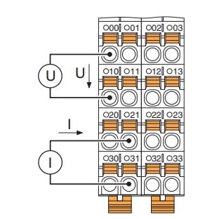
Figure 2. Examples of voltage (U) and current (I) input wiring for the PLCnext analog module. Image used courtesy of Phoenix Contact (page 7 of the datasheet)
For voltage inputs, connect the actual voltage signal into terminals 00 and 01, while the common (ground) connections are 10 and 11.
If you are using current devices, the current signal connects to terminals 20 and 21, and again, the common connection attaches to 30 and 31.
If you have one voltage and one current sensor, that’s no problem, but you must remember that terminals x0 (as in 00, 10, 20, and 30) comprise the first input, so select either the I or V input, then the x1 terminals are the second input, so use the other device.
In this module, x2 and x3 are the analog outputs, and they follow a similar wiring scheme.
For our own project, the sensor emits a 4-20 mA signal, so our signal wire connects to terminal 20, and terminal 30 is connected to the 0 vDC bus from the power supply.
Adding Analog Variables (Tags)
We have already explored the basic navigation around PLCnext Engineer, so we can recycle our previous project and open the IEC 61131-3 menu to access the variables.
Initially, we’ll only create our new analog input variable.
The format for the actual real-world process data items begins with the name assigned to the module, in our case “dio-1” for the digital I/O module, and “aio-1” for the analog module. Following the module name, add “/ IN” or “/ OUT” followed by the input number. Following this method for our analog input in the first input terminal, “aio-1 / IN01” becomes our process data item.
Interestingly, although the digital I/O begins with address 00, the analog addresses begin with 01.
The name I assigned to the variable was Distance_Sensor.

Figure 3. A new variable for the analog sensor. Image used courtesy of the author
Converting Hex to Decimal
By default, the analog input is a double word (DWORD) displayed in hex format. It might be easier to view this value as its decimal equivalent or perhaps even to convert it into mA or inches (or mm) since that’s ultimately the actual purpose of our sensor.
To begin this conversion, we need to make a placeholder variable in DINT format, and we’ll call it “Decimal_Value”. Note that this variable is NOT tied to any process data item. It’s only a virtual variable.

Figure 4. A new variable for the number conversion, but not attached to a physical I/O point. Image used courtesy of the author
Navigate to the Main task where the ladder programming exists. The conversion and computational blocks for this exercise are function blocks, so they will appear as FBD programming elements, not a ladder logic line.
Drag in a block called “TO_DINT” which will convert any data format into a DINT in decimal display format. We use our Distance_Sensor DWORD as the input, and the Decimal_Value DINT as the output.
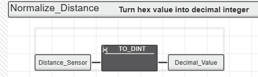
Figure 5. TO_DINT function block that converts the DWORD into a double integer. Image used courtesy of the author
Download and run the program, and you should be able to monitor the value in the IEC61131 variable window.
Calculating Distance in Inches
To produce a meaningful real-world value, we will convert the decimal analog value to an actual distance in inches from our ultrasonic sensor. If you have a potentiometer, maybe you want to know the angle of turn or perhaps the temperature from a thermocouple. Regardless, we’ll use the same process to obtain a result.
This process is called “scaling,” where we need 4x pieces of information:
- Bring the sensor to a close distance from a wall (a few inches). My value: 4
- Record the value of the Decimal_Value variable at this moment. My value: 5000
- Bring the sensor to a longer distance away from the wall. My value: 36
- Record the value of the Decimal_Value variable at this moment. My value: 28000
Actually, the Decimal_Value numbers were not quite this precise, I only rounded for the sake of easier math in this demo project.
We will use a 2-point entry method to obtain the slope and y-intercept. Even easier, you may prefer to use any online “slope intercept formula calculator,” which will prompt you for two (x, y) ordered points.
- X1 = 5000, Y1 = 4
- X2 = 28000, Y2 = 36
Using these values, we arrive at a slope intercept equation of y=(1/719)x - 3. Therefore, if we start with our X Decimal_Value, then divide by 719 and subtract 3, we should arrive at the distance in inches.
The PLCnext Engineer has the necessary mathematical function blocks for this operation.
I chose to save my final distance in a variable called “Actual_Signal_Current” to indicate that this is the current value of the sensor.
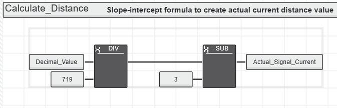
Figure 6. Creating a linear equation with integers (multiple or divide by the slope, then add or subtract the y-intercept). Image used courtesy of the author
Lighting up the Stack
Finally, we want to light up the stack lights, right?
Our goal will be three different intervals, from a low to high distance range. For the low distance range, use a single greater than "GT" function block. Set the comparison value to a fixed "10", which will energize the output for any distance greater than 10”.
Repeat the same process using a GT with fixed references set to 15” and 20”.
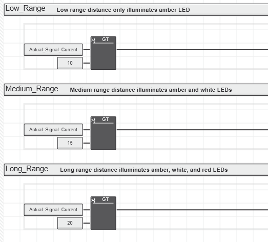
Figure 7. Consecutive ‘greater than’ comparisons are used to illuminate the LEDs as the distance increases. Image used courtesy of the author
At the far right ends of these rungs are the output coils for each ascending tier of the stack light. The network comments describe the behavior of each LED.
After downloading and starting the controller, we should have a fully functioning "bar graph" light stack that gives us a visual of the reading from the analog sensor.
Adding Analog to Digital
Those digital, or discrete, signals are an excellent way to control a process with fixed limits and boundaries, but analog sensors open so many doors to process optimization and catching problems before they become catastrophes. With the simplicity of today’s control equipment, paired with its versatility and capability, it’s easier than ever to capture those analog signals.