 Facebook
 Google
 GitHub
 Linkedin
Calibration Standards to Produce and Measure Physical Quantities
As previously defined, calibration refers to the checking and adjustment of an instrument so that its output faithfully corresponds to its input throughout a specified range. In order to calibrate an instrument, we must have some means of knowing the input and/or output quantities associated with the instrument under test. A substance or device used as a reference to compare against an instrument’s response is called a calibration standard. Simply put, a calibration standard is something we may compare the calibrated instrument to. Thus, any calibration can only be as good as the standard used.
What Are the Standards Used for Calibration?
Calibration standards fall into two broad categories: standards used to produce accurate physical quantities (e.g. pressure, temperature, voltage, current, etc.), and standards used to simply measure physical quantities to a high degree of accuracy. An example of the former would be the use of boiling water (at sea level) to produce a temperature of 100 degrees Celsius (212 degrees Fahrenheit) in order to calibrate a temperature gauge, whereas an example of the latter would be the use of a laboratory-quality precision thermometer to measure some arbitrary source of temperature in comparison to the temperature gauge being calibrated.
In metrology labs, the ultimate standards are based on fundamental constants of nature, and are called intrinsic standards. A modern example of an intrinsic standard for time is the so-called atomic clock, using isolated atoms of Cesium to produce frequencies which are inherently fixed and reproduceable world-wide. Instrument shops located in industrial facilities cannot afford the capital and consumable costs associated with intrinsic standards, and so must rely on other devices for their calibration purposes. Ideally, there should be a “chain” of calibration from any device used as a shop standard traceable all the way back to some intrinsic standard in a national-level or primary metrology lab.
Calibration standards used in instrument shops for industrial calibration work should therefore be periodically sent to a local metrology lab for re-standardization, where their accuracy may be checked against other (higher-level) standards which themselves are checked against even higher-level calibration standards, ultimately traceable all the way to intrinsic standards. In each step of the calibration “chain,” there is a progressive degree of measurement uncertainty. Intrinsic standards possess the least amount of uncertainty, while field instruments (e.g. pressure transmitters, temperature gauges, etc.) exhibit the greatest uncertainties.
Test Uncertainty Ratio (TUR)
It is important that the degree of uncertainty in the accuracy of a test instrument is significantly less than the degree of uncertainty we hope to achieve in the instruments we calibrate. Otherwise, calibration becomes a pointless exercise. This ratio of uncertainties is called the Test Uncertainty Ratio, or TUR. A good rule-of-thumb is to maintain a TUR of at least 4:1 (ideally 10:1 or better), the test equipment being many times more accurate (less uncertain) than the field instruments we calibrate with them.
I have personally witnessed the confusion and wasted time that results from trying to calibrate a field instrument to a tighter tolerance than what the calibration standard is capable of. In one case, an instrument technician attempted to calibrate a pneumatic pressure transmitter to a tolerance of \(\pm\) 0.25% of span using a test gauge that was only good for \(\pm\) 1% of the same span. This poor technician kept going back and forth, adjusting the transmitter’s zero and span screws over and over again in a futile attempt to reign in the transmitter’s response within the stated specification of \(\pm\) 0.25%. After giving up, he tested the test gauges by comparing three of them at once, tied together on a common air pressure tube. When he did this, it became clear that no two test gauges would consistently agree with each other within the specified tolerance over the 3 to 15 PSI range. As he raised and lowered the pressure, the gauges’ indications would deviate from one another far more than \(\pm\) 0.25% across the measurement range. Simply put, the inherent uncertainty of the gauges exceeded the uncertainty he was trying to calibrate the transmitter to. As a result, his calibration “standard” was in fact shifting on him as he performed the calibration. His actions were analogous to trying to set up a fixed-position cannon to repeatedly hit a moving target.
The lesson to be learned here is to always ensure the standards used to calibrate industrial instruments are reliably accurate (enough). No calibration standard is perfect, but perfection is not what we need. Our goal is to be accurate enough that the final calibration will be reliable within specified boundaries.
The next few subsections describe various standards used in instrument shops to calibrate industrial instruments.
Electrical Calibration Standards
Electrical calibration equipment – used to calibrate instruments measuring voltage, current, and resistance – must be periodically calibrated against higher-tier standards maintained by outside laboratories. In years past, instrument shops would often maintain their own standard cell batteries (often called Weston cells) as a primary voltage reference. These special-purpose batteries produced 1.0183 volts DC at room temperature with low uncertainty and drift, but were sensitive to vibration and non-trivial to actually use. Now, electronic voltage references have all but displaced standard cells in calibration shops and laboratories, but these references must be checked and adjusted for drift in order to maintain their NIST traceability.
One enormous benefit of electronic calibration references is that they are able to generate accurate currents and resistances in addition to voltage (and not just voltage at one fixed value, either!). Modern electronic references are digitally-controlled as well, which lends themselves well to automated testing in assembly-line environments, and/or programmed multi-point calibrations with automatic documentation of as-found and as-left calibration data. A photograph of some electronic calibration references appears here:

If a shop cannot afford one of these versatile references for benchtop calibration use, an acceptable alternative in some cases is to purchase a high-accuracy multimeter and equip the calibration bench with adjustable voltage, current, and resistance sources. These sources will be simultaneously connected to the high-accuracy multimeter and the instrument under test, and adjusted until the high-accuracy meter registers the desired value. The measurement shown by the instrument under test is then compared against the reference meter and adjusted until matching (to within the required tolerance).
The following illustration shows how a high-accuracy voltmeter could be used to calibrate a handheld voltmeter in this fashion:

It should be noted that the variable voltage source shown in this test arrangement need not be sophisticated. It simply needs to be variable (to allow precise adjustment until the high-accuracy voltmeter registers the desired voltage value) and stable (so the adjustment will not drift appreciably over time). The accuracy of your calibration in the previous circuit originates not from the variable voltage source, but rather from the high-accuracy multimeter used as the calibration standard. It is the high-accuracy multimeter that serves as the calibration reference here, not the voltage source – it is the high-accuracy multimeter that functions as the standard.
Temperature Calibration Standards
The most common technologies for industrial temperature measurement are electrical in nature: RTDs and thermocouples. As such, the standards used to calibrate such devices are the same standards used to calibrate electrical instruments such as digital multimeters (DMMs). For RTDs, this means a precision resistance standard such as a decade box used to precisely set known quantities of electrical resistance. For thermocouples, this means a precision potentiometer used to generate precise quantities of low DC voltage (in the millivolt range, with microvolt resolution).
Photographs of antique potentiometers used to calibrate thermocouple-sensing temperature instruments appear here:


Modern, electronic calibrators are also available now for RTD and thermocouple instrument calibration, capable of sourcing accurate quantities of electrical resistance and DC millivoltage for the simulation of RTD and thermocouple elements, respectively. A photograph of a Fluke model 525A laboratory standard is shown here:

Both the antique potentiometers and modern laboratory calibrators such as the Fluke 525A are self-contained sources useful for simulating the electrical outputs of temperature sensors. If you closely observe the potentiometer photos, you can see numbers engraved around the circumference of the dials, showing the user how much voltage the device output at any given setting.
Given an accurate enough voltmeter, it is possible to construct your own calibration potentiometer for simulating the millivoltage output of a thermocouple. A simple voltage divider set up to reduce the DC voltage of an ordinary variable-voltage power supply will suffice, so long as it provides fine enough adjustment:

Unlike the potentiometers of old, providing direct read-out of millivoltage at the potentiometer dial(s), we rely here on the accuracy of the precision multimeter to tell us when we have reached the required millivoltage with our power supply and voltage divider circuit. This means the high-accuracy multimeter functions as the calibration standard in this set-up, permitting the use of non-precision components in the rest of the circuit. Since the multimeter’s indication is the only variable being trusted as accurate when calibrating the thermocouple-input temperature transmitter, the multimeter is the only component in the circuit affecting the uncertainty of our calibration.
Electrically simulating the output of a thermocouple or RTD may suffice when the instrument we wish to calibrate uses a thermocouple or an RTD as its sensing element. However, there are some temperature-measuring instruments that are not electrical in nature: this category includes bimetallic thermometers, filled-bulb temperature systems, and optical pyrometers. In order to calibrate these types of instruments, we must accurately create the calibration temperatures in the instrument shop. In other words, the instrument to be calibrated must be subjected to an actual temperature of accurately known value.
Phase Shift Calibration
Even with RTDs and thermocouples – where the sensor signal may be easily simulated using electronic test equipment – there is merit in using an actual source of precise temperature to calibrate the temperature instrument. Simulating the voltage produced by a thermocouple at a precise temperature, for example, is fine for calibrating the instrument normally receiving the millivoltage signal from the thermocouple, but this calibration test does nothing to validate the accuracy of the thermocouple element itself! The best type of calibration for any temperature-measuring instrument, from the perspective of overall integrity, is to actually subject the sensing element to a precisely known temperature. For this we need special calibration equipment designed to produce accurate temperature samples on demand.
A time-honored standard for low-temperature industrial calibrations is pure water, specifically the freezing and boiling points of water. Pure water at sea level (full atmospheric pressure) freezes at 32 degrees Fahrenheit (0 degrees Celsius) and boils at 212 degrees Fahrenheit (100 degrees Celsius). In fact, the Celsius temperature scale is defined by these two points of phase change for water at sea level.
To use water as a temperature calibration standard, simply prepare a vessel for one of two conditions: thermal equilibrium at freezing or thermal equilibrium at boiling. “Thermal equilibrium” in this context simply means equal temperature throughout the mixed-phase sample. In the case of freezing, this means a well-mixed sample of solid ice and liquid water. In the case of boiling, this means a pot of water at a steady boil (vaporous steam and liquid water in direct contact). What you are trying to achieve here is ample contact between the two phases (either solid and liquid; or liquid and vapor) to eliminate hot or cold spots. When the entire water sample is homogeneous in temperature and heterogeneous in phase (i.e. a mix of different phases), the sample will have only one degree of thermodynamic freedom: its temperature is an exclusive function of atmospheric pressure. Since atmospheric pressure is relatively stable and well-known, this fixes the temperature at a constant value. For ultra-precise temperature calibrations in laboratories, the triple point of water is used as the reference. When water is brought to its triple point (i.e. all three phases of solid, liquid, and gas co-existing in direct contact with each other), the sample will have zero degrees of thermodynamic freedom, which means both its temperature and its pressure will become locked at stable values: pressure at 0.006 atmospheres, and temperature at 0.01 degrees Celsius.
The following photograph shows a triple-point cell for water, used as a laboratory calibration standard:

The major limitation of water as a temperature calibration standard is it only provides two points of calibration: 0 \(^{o}\)C and 100 \(^{o}\)C, with the latter being strongly pressure-dependent. If other reference temperatures are required for a calibration, some substance other than water must be used.
A variety of substances with known phase-change points have been standardized as fixed points on the International Practical Temperature Scale (ITS-90). The following list is a sample of some of these substances and their respective phase states and temperatures:
- Neon (triple point) = -248.6 \(^{o}\)C
- Oxygen (triple point) = -218.8 \(^{o}\)C
- Mercury (triple point) = -38.83 \(^{o}\)C
- Tin (freezing point) = 231.93 \(^{o}\)C
- Zinc (freezing point) = 419.53 \(^{o}\)C
- Aluminum (freezing point) = 660.32 \(^{o}\)C
- Copper (freezing point) = 1084.62 \(^{o}\)C
Substances at the triple point must be in thermal equilibrium with solid, liquid, and vaporous phases co-existing. Substances at the freezing point must be a two-phase mixture of solid and liquid (i.e. a liquid in the process of freezing, neither a completely liquid nor a completely solid sample). The physical principle at work in all of these examples is that of latent heat: the thermal energy exchange required to change the phase of a substance. So long as the minimum heat exchange requirement for complete phase change is not met, a substance in the midst of phase transition will exhibit a fixed temperature, and therefore behave as a temperature standard. Small amounts of heat gain or loss to such a sample will merely change the proportion of one phase to another (e.g. how much solid versus how much liquid), but the temperature will remain locked at a constant value until the sample becomes a single phase.
One major disadvantage of using phase changes to produce accurate temperatures in the shop is the limited availability of temperatures. If you need to create some other temperature for calibration purposes, you either need to find a suitable material with a phase change happening at that exact same temperature (good luck!) or you need to find a finely adjustable temperature source and use an accurate thermometer to compare your instrument under test against. The latter scenario is analogous to the use of a high-accuracy voltmeter and an adjustable voltage source to calibrate a voltage instrument: comparing one instrument (trusted to be accurate) against another (under test).
Oil Bath Calibrator
Laboratory-grade thermometers are relatively easy to secure. Variable temperature sources suitable for calibration use include oil bath and sand bath calibrators. These devices are exactly what they sound like: small pots filled with either oil or sand, containing an electric heating element and a temperature control system using a laboratory-grade (NIST-traceable) thermal sensor. In the case of sand baths, a small amount of compressed air is introduced at the bottom of the vessel to “fluidize” the sand so the grains move around much like the molecules of a liquid, helping the system reach thermal equilibrium. To use a bath-type calibrator, place the temperature instrument to be calibrated such the sensing element dips into the bath, then wait for the bath to reach the desired temperature.
An oil bath temperature calibrator is shown in the following photograph, with sockets to accept seven temperature probes into the heated oil reservoir:

This particular oil bath unit has no built-in indication of temperature suitable for use as the calibration standard. A standard-grade thermometer or other temperature-sensing element must be inserted into the oil bath along with the sensor under test in order to provide a reference indication useful for calibration.
Dry Block Temperature Calibrator
Dry-block temperature calibrators also exist for creating accurate calibration temperatures in the instrument shop environment. Instead of a fluid (or fluidized powder) bath as the thermal medium, these devices use metal blocks with blind (dead-end) holes drilled for the insertion of temperature-sensing instruments.
An inexpensive dry-block temperature calibrator intended for bench-top service is shown in this photograph:

This particular dry-block temperature calibrator does provide direct visual indication of the block temperature by means of a digital display on its front panel. If greater accuracy is desired, a laboratory reference-grade temperature sensor may be inserted into the same block along with the sensor being tested, and that reference-grade sensor relied upon as the temperature standard rather than the dry-block calibrator’s digital display.
Blackbody Calibrator
Optical temperature instruments require a different sort of calibration tool: one that emits radiation equivalent to that of the process object at certain specified temperatures. This type of calibration tool is called a blackbody calibrator, having a target area where the optical instrument may be aimed. Like oil and sand bath calibrators, a blackbody calibrator relies on an internal temperature sensing element as a reference, to control the optical emissions of the blackbody target at any specified temperature within a practical range.
Pressure Calibration Standards
In order to accurately calibrate a pressure instrument in a shop environment, we must create fluid pressures of known magnitude against which we compare the instrument being calibrated. As with other types of physical calibrations, our choice of standards falls into two broad categories: devices that inherently produce known pressures versus devices that accurately measure pressures created by some (other) adjustable source.
Deadweight Tester
A deadweight tester (sometimes referred to as a dead-test calibrator) is an example in the former category. These devices create accurately known pressures by means of precise masses and pistons of precise area:

After connecting the gauge (or other pressure instrument) to be calibrated, the technician adjusts the secondary piston to cause the primary piston to lift off its resting position and be suspended by oil pressure alone. So long as the mass placed on the primary piston is precisely known, Earth’s gravitational field is constant, and the piston is perfectly vertical, the fluid pressure applied to the instrument under test must be equal to the value described by the following equation:
\[P = {F \over A}\]
Where,
\(P\) = Fluid pressure
\(F\) = Force exerted by the action of gravity on the mass (\(F_{weight} = mg\))
\(A\) = Area of piston
The primary piston area, of course, is precisely set at the time of the deadweight tester’s manufacture and does not change appreciably throughout the life of the device.
A very simple deadweight tester unit appears in the next photograph, mounted to a yellow wooden base:

When sufficient pressure has been accumulated inside the tester to overcome the weight on the piston, the piston rises off its rest and “floats” on the pressurized oil, as shown in this close-up photograph:

A common operating practice for any deadweight tester is to gently spin the mass during testing so the primary piston continually rotates within its cylinder. Any motion will prevent static friction from taking hold, helping to ensure the only force on the primary piston is the force of the fluid within the deadweight tester.
Most modern deadweight testers include extra features such as hand pumps and bleed valves in addition to secondary pistons, to facilitate both rapid and precise operation. The next photograph shows a newer deadweight tester, with these extra features:

Pneumatic Deadweight Tester
There is also such a thing as a pneumatic deadweight tester. In these devices, a constant flow of gas such as compressed air or bottled nitrogen vents through a bleed port operated by the primary piston. The piston moves as necessary to maintain just enough gas pressure inside the unit to suspend the mass(es) against gravity. This gas pressure passes on to the instrument under test, just as liquid pressure in a hydraulic deadweight tester passes to the test instrument for comparison:

In fact, the construction and operation of a pneumatic deadweight tester is quite similar to a self-balancing (force-balance) pneumatic instrument mechanism with a baffle/nozzle assembly. A moving element opens or closes a variable restriction downstream of a fixed restriction to generate a varying pressure. In this case, that pressure directly operates the bleed vent to self-regulate gas pressure at whatever value is necessary to suspend the mass against gravity.
Deadweight testers (both hydraulic and pneumatic) lend themselves well to relatively high pressures, owing to the practical limitations of mass and piston area. You could use a deadweight tester to calibrate a 100 PSI pressure gauge used for measuring water mains pressure, for example, but you could not use a deadweight tester to calibrate a 0 to 1 "W.C. (zero to one inch water column) pressure gauge used to measure draft pressure in a furnace flue.
Manometer
For low-pressure calibrations, the simple manometer is a much more practical standard. Manometers, of course, do not generate pressure on their own. In order to use a manometer to calibrate a pressure instrument, you must connect both devices to a source of variable fluid pressure, typically instrument air through a precision pressure regulator:

The difference in liquid column heights (\(h\)) within the manometer shows the pressure applied to the gauge. As with the deadweight tester, the accuracy of this pressure measurement is bound by just a few physical constants, none of which are liable to sudden change. So long as the manometer’s liquid density is precisely known, Earth’s gravitational field is constant, and the manometer tubes are perfectly vertical, the fluid pressure indicated by the manometer must be equal to the value described by the following equation (two different forms given):
\[P = \rho gh \hspace{25pt} (or) \hspace{25pt} P = \gamma h\]
Where,
\(P\) = Fluid pressure
\(\rho\) = Mass density of fluid
\(\gamma\) = Weight density of fluid
\(g\) = Acceleration of gravity
\(h\) = Height difference between manometer liquid columns
Electronic Manometers
Of course, with pressure-measuring test instruments of suitable accuracy (preferably NIST-traceable), the same sort of calibration jig may be used for virtually any desired range of pressures:

When the electronic test gauge is designed for very low pressures (inches of water column), they are sometimes referred to as electronic manometers.
Slack Tube Manometers
Instrument calibrations performed in the field (i.e. in locations near or at the intended point of use rather than in a professionally-equipped shop) are almost always done this way: a pressure-generating source is connected to both the instrument under test and a trusted calibration gauge (“test gauge”), and the two indications are compared at several points along the calibrated range. Test equipment suitable for field pressure calibrations include slack-tube manometers made from flexible plastic tubing hung from any available anchor point near eye level, and test gauges typically of the helical bourdon tube variety. Portable electronic test gauges are also available for field use, many with built-in hand pumps for generating precise air pressures.
Wally Box
A noteworthy example of a pneumatic pressure calibrator for field use was a device manufactured by the Wallace & Tiernan corporation, affectionately called a Wally box by at least one generation of instrument technicians. A “Wally box” consisted of a large dial pressure gauge (several inches in diameter) with a multi-turn needle and a very fine scale, connected to a network of valves and regulators which were used to set different air pressures from any common compressed air source. The entire mechanism was housed in an impact-resistance case for ruggedness. One of the many nice features of this calibration instrument was a selector valve allowing the technician to switch between two different pressures output by independent pressure regulators. Once the two pressure regulator values were set to the instrument’s lower- and upper-range values (LRV and URV), it was possible to switch back and forth between those two pressures at will, making the task of adjusting an analog instrument with interactive zero and span adjustments much easier than it would have been to precisely adjust a single pressure regulator again and again.
Flow Calibration Standards
Most forms of continuous flow measurement are inferential; that is, we measure flow indirectly by measuring some other variable (such as pressure, voltage, or frequency) directly. With this in mind, we may usually achieve reasonable calibration accuracy simply by calibrating the primary sensor and replacing the flow element (if inspection proves necessary). In the case of an orifice plate used to measure fluid flow rate, this would mean calibrating the differential pressure transmitter to measure pressure accurately and replacing the orifice plate if it shows signs of wear.
In some cases, though, direct validation of flow measurement accuracy is needed. Most techniques of flow rate validation take the form of measuring accumulated fluid volume over time. This may prove to be complicated, especially if the fluids in question are hazardous in any way, and/or the flow rates are large, and/or the fluid is a gas or vapor.
For simple validation of liquid flow rates, the flow may be diverted from its normal path in the process and into a container where either accumulated volume or accumulated weight may be measured over time. If the rate of flow into this container is constant, the accumulated volume (or weight) should increase linearly over time. The actual flow rate may then be calculated by dividing the change in volume (\(\Delta V\)) by the time period over which the change in volume was measured (\(\Delta t\)). The resulting quotient is the average flow rate between those two points in time, which is an approximation of instantaneous flow rate:
\[{\Delta V \over \Delta t} = \hbox{ Average flow}\]
\[{\Delta V \over \Delta t} \approx {dV \over dt} = \hbox{ Instantaneous flow}\]
If a suitable vessel exists in the process with level-measuring capability (e.g. a liquid storage vessel equipped with a level transmitter), you may apply the same mathematical technique: use that vessel as an accumulator for the flow in question, tracking the accumulated (or lost) volume over time and then calculating \(\Delta V \over \Delta t\). The accuracy of this technique rests on some additional factors, though:
- The accuracy of the level transmitter (as a volume measuring instrument!)
- The ability to ensure only one flow path in or out of that vessel
The first condition listed here places significant limitations on the flow calibration accuracy one can achieve with this method. In essence, you are using the level instrument as the “test gauge” for the flow instrument, so it needs to be high-accuracy in order to achieve even reasonable accuracy for the flowmeter being calibrated.
Flow Prover
A more sophisticated approach for direct flow validation is the use of a device called a flow prover. A “flow prover” is a precision piston-and-cylinder mechanism used to precisely measure a quantity of liquid over time. Process flow is diverted through the prover, moving the piston over time. Sensors on the prover mechanism detect when the piston has reached certain positions, and time measurements taken at those different positions enable the calculation of average flow (\(\Delta V \over \Delta t\)).
Analytical Calibration Standards
An analyzer measures intrinsic properties of a substance sample such as its density, chemical content, or purity. Whereas the other types of instruments discussed in this chapter measure quantities incidental to the composition of a substance (pressure, level, temperature, and flow rate), an analyzer measures something related to the nature of substance being processed.
As previously defined, to calibrate an instrument means to check and adjust (if necessary) its response so the output accurately corresponds to its input throughout a specified range. In order to do this, one must expose the instrument to an actual input stimulus of precisely known quantity. This is no different for an analytical instrument. In order to calibrate an analyzer, we must exposed it to known quantities of substances with the desired physical and/or chemical properties (density, chemical composition, etc.). In other words, we need to use chemical standards.
A classic example of this is the calibration of a pH analyzer. pH is the measurement of hydrogen ion activity in an aqueous solution. The standard range of measurement is 0 pH to 14 pH, the number representing a negative power of 10 approximately describing the hydrogen ion molarity of the solution (how many moles of active hydrogen ions per liter of solution).
[pH buffer]
Buffer Solution
The pH of a solution is typically measured with a pair of special electrodes immersed in the solution, which generate a voltage proportional to the pH of the solution. In order to calibrate a pH instrument, you must have a sample of liquid solution with a known pH value. For pH instrumentation, such calibration solutions are called buffers, because they are specially formulated to maintain stable pH values even in the face of (slight levels of) contamination.
pH buffers may be purchased in liquid form or in powder form. Liquid buffer solutions may be used directly out of the bottle, while powdered buffers must be dissolved in appropriate quantities of de-ionized water to generate a solution ready for calibration use. Pre-mixed liquid buffers are convenient to use, but have a fairly limited shelf life. Powdered buffer capsules are generally superior for long-term storage, and also enjoy the advantage of occupying less storage space in their dry state than a liquid buffer solution.
The following photograph shows a few 7.00 pH (\(\pm\) 0.02 pH) buffer capsules ready to be mixed with water to form a usable buffer solution:

After preparing the buffer solution in a cup, the pH probe is inserted into the buffer solution and given time to stabilize. One stabilized, the pH instrument may be adjusted to register the proper pH value. Buffer solutions should not be exposed to ambient air for any longer than necessary (especially alkaline buffers such as 10.0 pH) due to contamination. Pre-mixed liquid buffer storage containers should be capped immediately after pouring into working cups. Used buffer solution should be discarded rather than re-used at a later date.
Gas Analyzers
Analyzers designed to measure the concentration of certain gases in air must be calibrated in a similar manner. Oxygen analyzers, for example, used to measure the concentration of free oxygen in the exhaust gases of furnaces, engines, and other combustion processes must be calibrated against known standards of oxygen concentration. An oxygen analyzer designed to measure oxygen concentration over a range of ambient (20.9% oxygen) to 0% oxygen may be calibrated with ambient air as one of the standard values, and a sample of pure nitrogen gas (containing 0% oxygen) as the other standard value. An oxygen analyzer intended for the measurement of oxygen concentrations in excess of ambient air would require a different standard, most likely a sample of 100% pure oxygen, as a calibration reference.
An analyzer designed to measure the concentration of hydrogen sulfide (H\(_{2}\)S), a toxic gas produced by anaerobic bacterial decomposition of organic matter, will require a sample of gas with a precisely known concentration of hydrogen sulfide mixed in it as a calibration reference. A typical reference gas concentration might be 25 or 50 parts per million (ppm). Gas mixtures with such precise concentration values as this may be purchased from chemical laboratories for the purpose of calibrating concentration analyzers, and are often referred to as span gases because they are used to set the span of analyzer instruments.
Analytical instruments are generally subject to greater drifting over time than instruments that measure incidental quantities such as pressure, level, temperature, or flow rate. It is not uncommon for instrument technicians to be tasked with daily calibration checks of certain instruments responsible for monitoring atmospheric or water emissions at industrial facilities. For this reason, it is often practical to equip such critical analyzers with self-calibration systems. A self-calibration system is a system of solenoid (electrically controlled on-off) valves and reference gas bottles set up in such a way that a computer is able to switch the analyzer off-line and subject it to standard reference gases on a regular schedule to check calibration. Many analyzers are programmed to automatically calibrate themselves against these reference gases, thus eliminating tedious work for the instrument technician.
A typical self-calibration system for a gas analyzer might look like this:
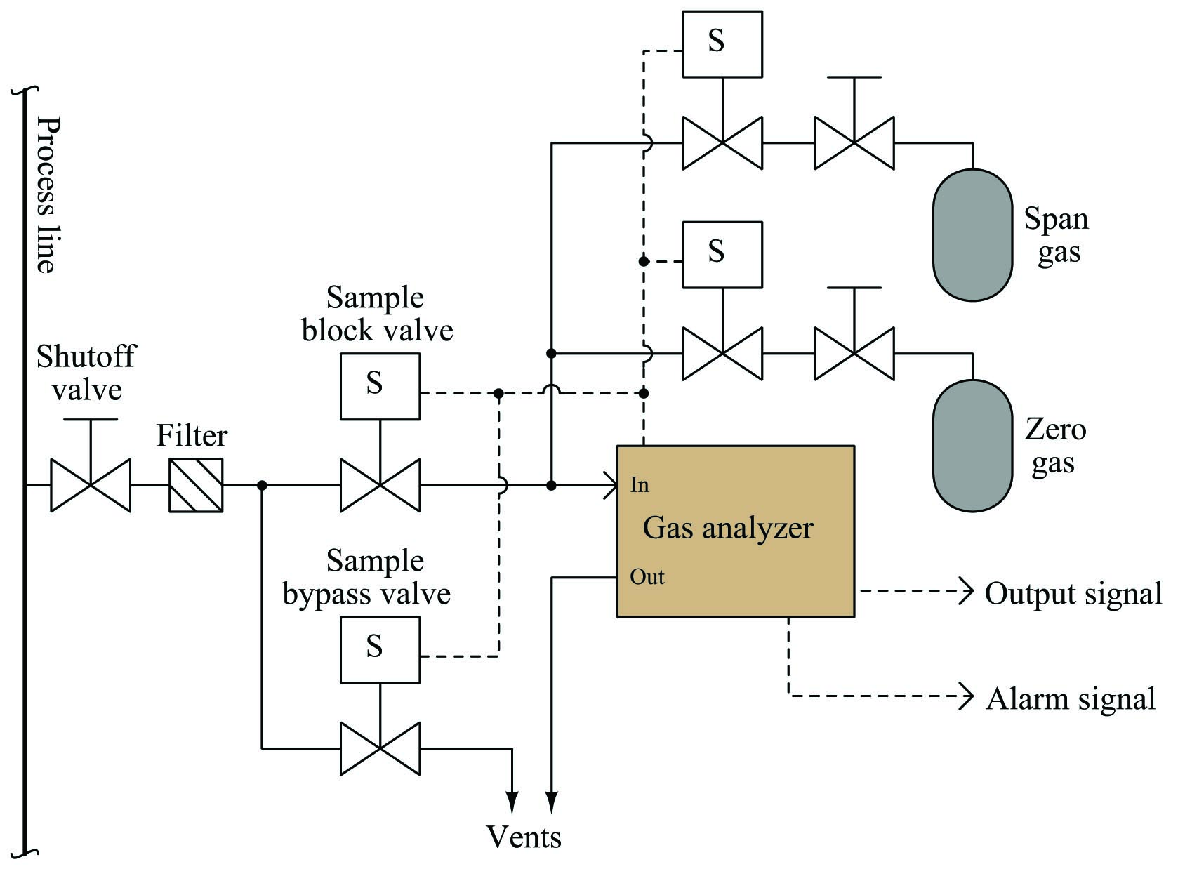
The gas analyzer is equipped with its own auto-calibration controls and programming, allowing it to periodically shut off the process sample and switch to known reference gases for “zero” and “span” calibration checks. If these checks indicate excessive drift or any other questionable results, the analyzer has the ability to flag a maintenance alarm to alert an instrument technician to a potential problem that may require servicing. This sort of self-calibration and self-diagnostic capability saves the instrument technician from having to spend substantial time running manual calibration checks, yet alerts the technician if anything is in need of actual repair. Barring any component failures within this system, the only maintenance this system will need is periodic replacement of the calibration gas bottles.
