 Facebook
 Google
 GitHub
 Linkedin
Safety Instrumented Functions and Systems
A Safety Instrumented Function, or SIF, is one or more components designed to execute a specific safety-related task in the event of a specific dangerous condition. The over-temperature shutdown switch inside a clothes dryer or an electric water heater is a simple, domestic example of an SIF, shutting off the source of energy to the appliance in the event of a detected over-temperature condition. Safety Instrumented Functions are alternatively referred to as Instrument Protective Functions, or IPFs.
A Safety Instrumented System, or SIS, is a collection of SIFs designed to bring an industrial process to a safe condition in the event of any dangerous detected conditions. Also known as Emergency Shutdown (ESD) or Protective Instrument Systems (PIS), these systems serve as an additional “layer” of protection against process equipment damage, adverse environmental impact, and/or human injury beyond the protection normally offered by a properly operating regulatory control system. Like all automatic control systems, an SIS consists of three basic sections: (1) Sensor(s) to detect a dangerous condition, (2) Controller to decide when to shut down the process, and (3) Final control element(s) to actually perform the shutdown action necessary to bring the process to a safe condition. Sensors may consist of process switches and/or transmitters separate from the regulatory control system. The controller for an SIS is usually called a logic solver, and is also separate from the regular control system. The final control elements for an SIS may be special on/off valves (often called “chopper” valves) or override solenoids used to force the normal control valve into a shutdown state.
Some industries, such as chemical processing and nuclear power, have extensively employed safety instrumented systems for many decades. Likewise, automatic shutdown controls have been standard on steam boilers and combustion furnaces for years. The increasing capability of modern instrumentation, coupled with the realization of enormous costs (both social and fiscal) resulting from industrial disasters has pushed safety instrumentation to new levels of sophistication and new breadths of application. It is the purpose of this section to explore some common safety instrumented system concepts as well as some specific industrial applications.
One of the challenges inherent to safety instrumented system design is to balance the goal of maximum safety against the goal of maximum economy. If an industrial manufacturing facility is equipped with enough sensors and layered safety shutdown systems to virtually ensure no unsafe condition will ever prevail, that same facility will be plagued by “false alarm” and “spurious trip” events where the safety systems malfunction in a manner detrimental to the profitable operation of the facility. In other words, a process system designed with an emphasis on automatic shut-down will probably shut down more frequently than it actually needs to. While the avoidance of unsafe process conditions is obviously a noble goal, it cannot come at the expense of economically practical operation or else there will be no reason for the facility to exist at all. A safety system must fulfill its intended protective function, but not at the expense of compromising the intended purpose of the facility.
This tension is understood well within the electric power generation and distribution industries. Faults in high-voltage electrical lines can be very dangerous, as well as destructive to electrical equipment. For this reason, special protective devices are placed within power systems to monitor conditions and halt the flow of electricity if those conditions become threatening. However, the very presence of these devices means it is possible for power to accidently shut off, causing unnecessary power outages for customers. In the electrical industry, the word “dependability” refers to the probability that the protective systems will cut power when required. By contrast, the word “security” is used in the electrical industry to refer to the avoidance of unnecessary outages. We will apply these terms to general process systems.
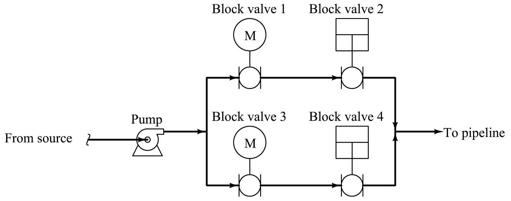
To illustrate the tension between dependability and security in a fluid process system, we may analyze a double-block shutoff valve system for a petroleum pipeline:

The safety function of these block valves is, of course, to shut off flow from the petroleum source to the distribution pipeline in the event that the pipeline suffers a leak or rupture. Having two block valves in “series” adds an additional layer of safety, in that only one of the block valves need shut to fulfill the safety (dependability) function. Note the use of two different valve actuator technologies: one electric (motor) and the other a piston (either pneumatic or hydraulically actuated). This diversity of actuator technologies helps avoid common-cause failures, helping to ensure both valves will not simultaneously fail due to a single cause.
However, the typical operation of the pipeline demands both block valves be open in order for petroleum to flow through it. The presence of redundant (dual) block valves, while increasing safety, decreases security for the pipeline. If either of the two block valves happened to fail shut when there was no need to shut off the pipeline, flow through the pipeline would needlessly halt. Having two series-plumbed block valves instead of one block valve increases the probability of unnecessary pipeline shutdowns.
A precise notation useful for specifying dependability and security in redundant systems compares the number of redundant elements necessary to achieve the desired result compared to the total number of redundant elements. If the desired result for our double-block valve array is to shut down the pipeline in the event of a detected leak or rupture, we would say the system is one out of two (1oo2) redundant for dependability. In other words, only one out of the two redundant valves needs to function properly (shut off) in order to bring the pipeline to a safe condition. If the desired result is to allow flow through the pipeline when the pipeline is leak-free, we would say the system is two out of two (2oo2) redundant for security. This means both of the two block valves need to function properly (open up) in order to allow petroleum to flow through the pipeline.
This numerical notation showing the number of essential elements versus number of total elements is often referred to as MooN (“\(M\) out of \(N\)”) notation, or sometimes as NooM (“\(N\) out of \(M\)”) notation. When discussing safety instrumented systems, the ISA standard 84 defines redundancy in terms of the number of agreeing channels necessary to perform the safety (shutdown) function – in other words, the ISA’s usage of “MooN” notation implies dependability, rather than security.
A complementary method of quantifying dependability and security for redundant systems is to label in terms of how many element failures the system may sustain while still achieving the desired result. For this series set of double block valves, the safety (shutdown) function has a fault tolerance of one (1), since one of the valves may fail to shut when called upon but the other valve remains sufficient in itself to shut off the flow of petroleum to the pipeline. The normal operation of the system, however, has a fault tolerance of zero (0). Both block valves must open up when called upon in order to establish flow through the pipeline.
It should be clearly evident that a series set of block valves emphasizes dependability (the ability to shut off flow through the pipeline when needed) at the expense of security (the ability to allow normal flow through the pipeline when there is no leak). We may now analyze a parallel block valve scheme to compare its redundant characteristics:

In this system, the safety (dependability) redundancy function is 2oo2, since both block valves would have to shut off in order to bring the pipeline to a safe condition in the event of a detected pipeline leak. However, security would be 1oo2, since only one of the two valves would have to open up in order to establish flow through the pipeline. Thus, a parallel block valve array emphasizes production (the ability to allow flow through the pipeline) over safety (the ability to shut off flow through the pipeline).
Another way to express the redundant behavior of the parallel block valve array is to say that the safety function has a fault tolerance of zero (0), while the production function has a fault tolerance of one (1).
One way to avoid compromises between dependability and security is to increase the number of redundant components, forming arrays of greater complexity. Consider this quadruple block valve array, designed to serve the same function on a petroleum pipeline:
In order to fulfill its safety function of shutting off the flow of petroleum to the pipeline, both parallel pipe “branches” must be shut off. At first, this might seem to indicate a two-out-of-four (2oo4) dependability, because all we would need is for one valve in each branch (two valves total) out of the four valves to shut off in order to shut off flow to the pipeline. We must remember, however, that we do not have the luxury of assuming idealized faults. If only two of the four valves function properly in shutting off, they just might happen to be two valves in the same branch, in which case two valves properly functioning is not enough to guarantee a safe pipeline condition. Thus, this redundant system actually exhibits three-out-of-four (3oo4) dependability (i.e. it has a safety fault tolerance of one), because we need three out of the four block valves to properly shut off in order to guarantee a safe pipeline condition.
Analyzing this quadruple block valve array for security, we see that three out of the four valves need to function properly (open up) in order to guarantee flow to the pipeline. Once again, it may appear at first as though all we need are two of the four valves to open up in order to establish flow to the pipeline, but this will not be enough if those two valves happen to be in different parallel branches. So, this system exhibits three-out-of-four (3oo4) security (i.e. it has an production fault tolerance of one).
SIS sensors
Perhaps the simplest form of sensor providing process information for a safety instrumented function is a process switch. Examples of process switches include temperature switches, pressure switches, level switches, and flow switches. SIS sensors must be properly calibrated and configured to indicate the presence of a dangerous condition. They must be separate and distinct from the sensors used for regulatory control, in order to ensure a level of safety protection beyond that of the basic process control system.
Referring to the clothes dryer and domestic water heater over-temperature shutdown switches, these high-temperature shutdown sensors are distinctly separate from the regulatory (temperature-controlling) sensors used to maintain the appliance’s temperature at setpoint. As such, they should only ever spring into action in the event of a high-temperature failure of the basic control system. That is, the over-temperature safety switch on a clothes dryer or a water heater should only ever reach its high-temperature limit if the normal temperature control system of the appliance fails to do its job of regulating temperature to normal levels.
Industrial Safety Instrumented Systems (SIS) always use dedicated transmitters and/or process switches to detect abnormal process conditions. As a rule, one should always use independent sensors for safety shutdown, and never rely on the regulatory control sensor(s) for safety functions. In the electric power industry we see this same segregation of functions: separate instrument transformers (PTs and CTs) are used to sense line voltage and line current for metering and control (regulatory) versus for protective relay (safety shutdown) equipment. It would be foolish to depend on one sensor for both functions. We see this general rule applied even in home appliances such as electric water heaters: the safety shutdown temperature switch is a separate component from the thermostat switch used to regulate water temperature. This way, a failure in the regulatory sensor does not compromise the integrity of the safety function.
A modern trend in safety instrumented systems is to use continuous process transmitters rather than discrete process switches to detect dangerous process conditions. Any process transmitter – analog or digital – may be used as a safety shutdown sensor if its signal is compared against a “trip” limit value by a comparator relay or function block. This comparator function provides an on-or-off (discrete) output based on the transmitter’s signal value relative to the trip point.
A simplified example of a continuous transmitter used as a discrete alarm and trip device is shown here, where analog comparators generate discrete “trip” and “alarm” signals based on the measured value of liquid in a vessel. Note the necessity of two level switches on the other side of the vessel to perform the same dual alarm and trip functions:

Benefits to using a continuous transmitter instead of discrete switches include the ability to easily change the alarm or trip value, and better diagnostic capability. The latter point is not as obvious as the former, and deserves more explanation. A transmitter continuously measuring liquid level will produce an output signal that varies over time with the measured process variable. A “healthy” transmitter should therefore exhibit a continuously changing output signal, proportional to the degree of change in the process. Discrete process switches, in contrast to transmitters, provide no indication of “healthy” operation. The only time a process switch should ever change states is when its trip limit is reached, which in the case of a safety shutdown sensor indicates a dangerous (rare) condition. A process switch showing a “normal” process variable may indeed be functional and indicating properly, but it might also be failed and incapable of registering a dangerous condition should one arise – there is no way to tell by monitoring its un-changing status. The continuously varying output of a process transmitter therefore serves as an indicator of proper function.
In applications where Safety Instrumented Function (SIF) reliability is paramount, redundant transmitters may be installed to yield additional reliability. The following photograph shows triple-redundant transmitters measuring liquid flow by sensing differential pressure dropped across an orifice plate:

A single orifice plate develops the pressure drop, with the three differential pressure transmitters “tubed” in parallel with each other, all the “high” side ports connected together through common impulse tubing and all the “low” side ports connected together through common impulse tubing. These particular transmitters happen to be FOUNDATION Fieldbus rather than 4-20 mA analog electronic. The yellow instrument tray cable (ITC) used to connect each transmitter to a segment coupling device may be clearly seen in this photograph.
The “trick” to using redundant transmitters is to have the system self-determine what the actual process value is in the event one or more of the redundant transmitters disagree with each other. Voting is the name given to this important function, and it often takes the form of signal selector functions:

Multiple selection criteria are typically offered by “voting” modules, including high, low, average, and median. A “high” select voter would be suitable for applications where the dangerous condition is a large measured value, the voting module selecting the highest-valued transmitter signal in an effort to err on the side of safety. This would represent a 1oo3 safety redundancy (since only one transmitter out of the three would have to register beyond the high trip level in order to initiate the shutdown). A “low” select voter would, of course, be suitable for any application where the dangerous condition is a small measured value (once again providing a 1oo3 safety redundancy).
The “average” selection function merely calculates and outputs the mathematical average of all transmitter signals – a strategy prone to problems if one of the redundant transmitters happens to fail in the “safe” direction (thus skewing the average value away from the “dangerous” direction and thereby possibly causing the system to respond to an actual dangerous condition later than it should).
The median select criterion is very useful in safety systems because it effectively ignores any measurements deviating substantially from the others. Median selector functions may be constructed of high- and low-select function blocks in either of the following manners:

Three transmitters filtered through a median select function effectively provide a 2oo3 safety redundancy, since just a single transmitter registering a value beyond the safety trip point would be ignored by the voting function. Two or more transmitters would have to register values past the trip point in order to initiate a shutdown.
It should be stressed that redundant transmitter strategies are only effective if the transmitters all sense the exact same process variable, and if their failure modes are independent (i.e. no common-cause failure modes exist). If, for example, a set of redundant transmitters are attached to the process at different points such that they may legitimately sense different measurement values, the effectiveness of their redundancy will be compromised. Similarly, if a set of redundant transmitters are susceptible to failure from a shared condition (e.g. multiple liquid level transmitters that may be fooled by changes in process fluid density), then reliability will suffer.
SIS controllers (logic solvers)
Control hardware for safety instrumented functions should be separate from the control hardware used to regulate the process, if only for the simple reason that the SIF exists to bring the process to a safe state in the event of any unsafe condition arising, including dangerous failure of the basic regulatory controls. If a single piece of control hardware served the dual purposes of regulation and shutdown, a failure within that hardware resulting in loss of regulation (normal control) would not be protected because the safety function would be disabled by the same fault.
Safety controls are usually discrete with regard to their output signals. When a process needs to be shut down for safety reasons, the steps to implement the shutdown often take the form of opening and closing certain valves fully rather than partially. This sort of all-or-nothing control action is most easily implemented in the form of discrete signals triggering solenoid valves or electric motor actuators. A digital controller specially designed for and tasked with the execution of safety instrumented functions is usually called a logic solver, or sometimes a safety PLC, in recognition of this discrete-output nature.
A photograph of a “safety PLC” used as an SIS in an oil refinery processing unit is shown here, the controller being a Siemens “Quadlog” model:

Some logic solvers such as the Siemens Quadlog are adaptations of standard control systems (in the case of the Quadlog, its standard counterpart is called APACS). In the United States, where Rockwell’s Allen-Bradley line of programmable logic controllers holds the dominant share of the PLC market, a version of the ControlLogix 5000 series called GuardLogix is manufactured specifically for safety system applications. Not only are there differences in hardware between standard and safety controllers (e.g. redundant processors), but some of the programming instructions are unique to these safety-oriented controllers as well.
An example of a safety-specific programming instruction is the GuardLogix DCSRT instruction, which compares two redundant input channels for agreement before activating a “start” bit which may be used to start some equipment function such as an electric motor:

In this case, the DCSRT instruction looks for two discrete inputs to be in the correct complementary states (Channel A = 1 and Channel B = 0) before allowing a motor to start. These states must not conflict for a time-span longer than 50 milliseconds, or else the DCSRT instruction will set a “Fault Present” (FP) bit. As you can see, the form-C pushbutton contacts are wired to two discrete inputs on the GuardLogix PLC, giving the PLC dual (complementary) indication of the switch status.
For specialized and highly critical applications, dedicated safety controllers exist which share no legacy with standard control platforms. Triconex and ICS-Triplex are two such manufacturers, producing triple-modular redundant (TMR) control systems implementing 2oo3 voting at the hardware level, with redundant signal conditioning I/O circuits, redundant processors, and redundant communication channels between all components. The nuclear power industry boasts a wide array of application-specific digital control systems, with triple (or greater!) component redundancy for extreme reliability. An example of this is Toshiba’s TOSMAP system for boiling-water nuclear power reactors, the digital controller and electro-hydraulic steam turbine valve actuator subsystem having a stated MTBF of over 1000 years!
SIS final control elements
When a dangerous condition in a volatile process is sensed by process transmitters (or process switches), triggering a shutdown response from the logic solver, the final control elements must move with decisive and swift action. Such positive response may be obtained from a standard regulatory control valve (such as a globe-type throttling valve), but for more critical applications a rotary ball or plug valve may be more suitable. If the valve in question is used for safety shutdown purposes only and not regulation, it is often referred to as a chopper valve for its ability to “chop” (shut off quickly and securely) the process fluid flow. A more formal term for this is an Emergency Isolation Valve, or EIV.
Some process applications may tolerate the over-loading of both control and safety functions in a single valve, using the valve to regulate fluid flow during normal operation and fully stroke (either open or closed depending on the application) during a shutdown condition. A common method of achieving this dual functionality is to install a solenoid valve in-line with the actuating air pressure line, such that the valve’s normal pneumatic signal may be interrupted at any moment, immediately driving the valve to a fail-safe position at the command of a discrete “trip” signal.
Such a “trip” solenoid (sometimes referred to as a dump solenoid, because it “dumps” all air pressure stored in the actuating mechanism) is shown here, connected to a fail-closed (air-to-open) control valve:

Compressed air passes through the solenoid valve from the I/P transducer to the valve’s pneumatic diaphragm actuator when energized, the letter “E” and arrow showing this path in the diagram. When de-energized, the solenoid valve blocks air pressure coming from the I/P and vents all air pressure from the valve’s actuating diaphragm as shown by the letter “D” and arrow. Venting all actuating air pressure from a fail-closed valve will cause the valve to fail closed, obviously.
If we wished to have the valve fail open on demand, we could use the exact same solenoid and instrument air plumbing, but swap the fail-closed control valve for a fail-open control valve. When energized (regular operation), the solenoid would pass variable air pressure from the I/P transducer to the valve actuator so it could serve its regulating purpose. When de-energized, the solenoid would force the valve to the fully-open position by “dumping” all air pressure from the actuator.
For applications where it is safer to lock the control valve in its last position than to have it fail either fully closed or fully open, we might elect to use a solenoid valve in a different manner:

Here, de-energization of the solenoid valve causes the I/P transducer’s air pressure output to vent, while trapping and holding all air pressure inside the actuator at the trip time. Regardless of the valve’s “natural” fail-safe state, this system forces the valve to lock position until the solenoid is re-energized.
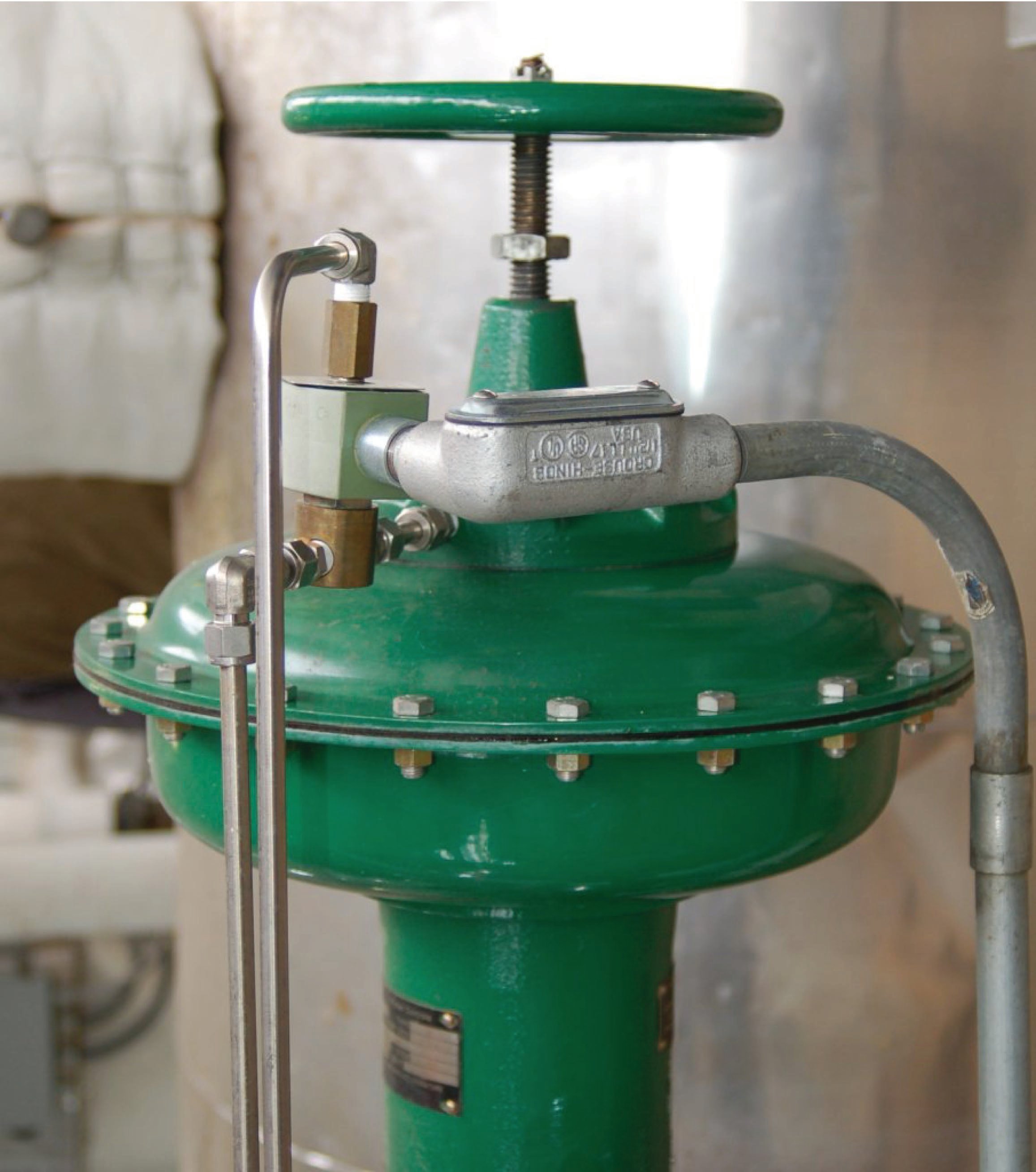
An example of a trip solenoid installed on a control valve appears in the following photograph. This valve also happens to have a hand jack wheel installed in the actuating mechanism, allowing a human operator to manually override the valve position by forcing it closed (or open) when the hand wheel is turned sufficiently:
Of all the components of a Safety Instrumented System (SIS), the final control elements (valves) are generally the least reliable, contributing most towards the system’s probability of failure on demand (PFD). Sensors generally come in at second place in their contribution toward unreliability, and logic solvers a distant third place. Redundancy may be applied to control elements by creating valve networks where the failure of a single valve does not cause the system as a whole to fail. Unfortunately, this approach is extremely expensive, as valves have both high capital and high maintenance costs compared to SIS sensors and logic solvers.
A less expensive approach than redundancy to increasing safety valve reliability is to perform regular proof tests of their operation. This is commonly referred to in the industry as partial stroke testing. Rather than proof-test each safety valve to its full travel, which would interrupt normal process operations, the valve is commanded to move only part of its full travel. If the valve responds well to this “partial stroke” test, there is a high probability that it is able to move all the way, thus fulfilling the basic requirements of a proof test without actually shutting the process down.
Safety Integrity Levels
A common way of ranking the dependability of a Safety Instrumented Function (SIF) is to use a simple numerical scale from one to four, with four being extremely dependable and one being only moderately dependable:
& Availability (RSA) & on Demand (PFD) \cr
| SIL number | Required Safety | Probability of Failure |
|---|---|---|
| 1 | 90% to 99% | 0.1 to 0.01 |
| 2 | 99% to 99.9% | 0.01 to 0.001 |
| 3 | 99.9% to 99.99% | 0.001 to 0.0001 |
| 4 | 99.99% to 99.999% | 0.0001 to 0.00001 |
The Required Safety Availability (RSA) value is synonymous with dependability: the probability that a Safety Instrumented Function will perform its duty when faced with a dangerous process condition. Conversely, the Probability of Failure on Demand (PFD) is synonymous with undependability: the mathematical complement of RSA (PFD = 1 \(-\) RSA), expressing the probability that the SIF will fail to perform as needed, when needed.
Conveniently, the SIL number matches the minimum number of “nines” in the Required Safety Availability (RSA) value. For instance, a safety instrumented function with a Probability of Failure on Demand (PFD) of 0.00073, will have an RSA value of 99.927%, which equates to a SIL 3 rating.
It is important to understand what SIL is, and what SIL is not. The SIL rating refers to the reliability of a safety function, not to individual components of a system nor to the entire process itself. An overpressure protection system on a chemical reactor process with a SIL rating of 2, for example, has a Probability of Failure on Demand between 0.01 and 0.001 for the specific shutdown function as a whole. This PFD value incorporates failure probabilities of the sensor(s), logic solver, final control element(s), and the process piping including the reactor vessel itself plus any relief valves and other auxiliary equipment. If there arises a need to improve the PFD of this reactor’s overpressure protection, safety engineers have a variety of options at their disposal for doing so. The safety instruments themselves might be upgraded, a different redundancy strategy implemented, preventive maintenance schedules increased in frequency, or even process equipment changed to make an overpressure event less likely.
SIL ratings do not apply to an entire process. It is quite possible that the chemical reactor mentioned in the previous paragraph with an overpressure protection system SIL rating of 3 might have an overtemperature protection system SIL rating of only 2, due to differences in how the two different safety systems function.
Adding to this confusion is the fact that many instrument manufacturers rate their products as approved for use in certain SIL-rated applications. It is easy to misunderstand these claims, thinking that a safety instrumented function will be rated at some SIL value simply because instruments rated for that SIL value are used to implement it. In reality, the SIL value of any safety function is a much more complex determination. It is possible, for instance, to purchase and install a pressure transmitter rated for use in SIL 2 applications, and have the safety function as a whole be less than 99% reliable (PFD greater than 0.01, or a SIL level no greater than 1) due to the effect of Lusser’s Law.
As with so many other complex calculations in instrumentation engineering, there exist software packages with all the necessary formulae pre-programmed for engineers and technicians alike to use for calculating SIL ratings of safety instrumented functions. These software tools not only factor in the inherent reliability ratings of different system components, but also correct for preventive maintenance schedules and proof testing intervals so the user may determine the proper maintenance attention required to achieve a given SIL rating.
SIS example: burner management systems
One “classic” example of an industrial automatic shutdown system is a Burner Management System (or BMS) designed to monitor the operation of a combustion burner and shut off the fuel supply in the event of a dangerous condition. Sometimes referred to as flame safety systems, these systems watch for such potentially dangerous conditions as low fuel pressure, high fuel pressure, and loss of flame. Other dangerous conditions related to the process being heated (such as low water level for a steam boiler) may be included as additional trip conditions.
The safety shutdown action of a burner management system is to halt the flow of fuel to the burner in the event of any hazardous detected condition. The final control element is therefore one or more shutoff valves (and sometimes a vent valve in addition) to positively stop fuel flow to the burner.
A typical ultraviolet flame sensor appears in this photograph:

This flame sensor is sensitive to ultraviolet light only, not to visible or infrared light. The reason for this specific sensitivity is to ensure the sensor will not be “fooled” by the visible or infrared glow of hot surfaces inside the firebox if ever the flame goes out unexpectedly. Since ultraviolet light is emitted only by an active gas-fueled flame, the sensor acts as a true flame detector, and not a heat detector.
One of the more popular models of fuel gas safety shutoff valve used in the United States for burner management systems is shown here, manufactured by Maxon:

This particular model of shutoff valve has a viewing window on it where a metal tag linked to the valve mechanism marked “Open” (in red) or “Shut” (in black) positively indicates the valve’s mechanical status. Like most safety shutoff valves on burner systems, this valve is electrically actuated, and will automatically close by spring tension in the event of a power loss.
Another safety shutoff valve, this one manufactured by ITT, is shown here:

Close inspection of the nameplate on this ITT safety valve reveals several important details. Like the Maxon safety valve, it is electrically actuated, with a “holding” current indicated as 0.14 amps at 120 volts AC. Inside the valve is an “auxiliary” switch designed to actuate when the valve has mechanically reached the full “open” position. An additional switch, labeled valve seal overtravel interlock, indicates when the valve has securely reached the full “shut” position. This “valve seal” switch generates a proof of closure signal used in burner management systems to verify a safe shutdown condition of the fuel line. Both switches are rated to carry 15 amps of current at 120 VAC, which is important when designing the electrical details of the system to ensure the switch will not be tasked with too much current.
A simple P&ID for a gas-fired combustion burner system is shown here. The piping and valving shown is typical for a single burner. Multiple-burner systems are often equipped with individual shutoff valve manifolds and individual fuel pressure limit switches. Each burner, if multiple exist in the same furnace, must be equipped with its own flame sensor:

Note the use of double-block and bleed shutdown valves to positively isolate the fuel gas supply from the burner in the event of an emergency shutdown. The two block valves are specially designed for the purpose (such as the Maxon and ITT safety valves previously shown), while the bleed valve is often nothing more than an ordinary electric solenoid valve.
Most burner management systems are charged with a dual role: both to manage the safe shutdown of a burner in the event of a hazardous condition, and the safe start-up of a burner in normal conditions. Start-up of a large industrial burner system usually includes a lengthy purge time prior to ignition where the combustion air damper is left wide-open and the blower running for several minutes to positively purge the firebox of any residual fuel vapors. After the purge time, the burner management system will ignite the burner (or sometimes ignite a smaller burner called the pilot, which in turn will light the main burner). A burner management system executes all these pre-ignition and timing functions to ensure the burners will ignite safely and without incident.
While many industrial burners are managed by electromechanical relay or analog electronic control systems, the modern trend is toward microprocessor-based digital electronic controls. One popular system is the Honeywell 7800 series burner control system, an example of which is shown in this photograph:

Microprocessor controls provide numerous advantages over relay-based and analog electronic burner management systems. Timing of purge cycles is far more accurate with microprocessor control, and the requisite purge time is more difficult to override. Microprocessor-based burner controls usually have digital networking capability as well, allowing the connection of multiple controls to a single computer for remote monitoring.
The Honeywell 7800 series additionally offers local “annunciator” modules to visually indicate the status of permissive (interlock) contacts, showing maintenance personnel which switches are closed and what state the burner control system is in:

The entire “gas train” piping system for a dual-fuel boiler at a wastewater treatment facility appears in the following photograph. Note the use of double-block and bleed valves on both “trains” (one for utility-supplied natural gas and the other for “sludge gas” produced by the facility’s anaerobic digesters), the block valves for each train happening to be of different manufacture. A Honeywell 7800 flame safety control system is located in the blue enclosure:

SIS example: water treatment oxygen purge system
One of the processes of municipal wastewater treatment is the aerobic digestion of organic matter by bacteria. This process emulates one of many waste-decomposition processes in nature, performed on an accelerated time frame for the needs of large wastewater volumes in cities. The process consists of supplying naturally occurring bacteria within the wastewater with enough oxygen to metabolize the organic waste matter, which to the bacteria is food. In some treatment facilities, this aeration is performed with ambient air. In other facilities, it is performed with nearly pure oxygen.
Aerobic decomposition is usually part of a larger process called activated sludge, whereby the effluent from the decomposition process is separated into solids (sludge) and liquid (supernatant), with a large fraction of the sludge recycled back to the aerobic chamber to sustain a healthy culture of bacteria and also ensure adequate retention time for decomposition to occur. Separating liquids from solids and recycling the solids ensures a short retention time for the liquid (allowing high processing rates) and a long retention time for the solids (ensuring thorough digestion of organic matter by the bacteria).
A simplified P&ID of an activated sludge water treatment system is shown here, showing how both the oxygen flow into the aeration chamber and the sludge recycle flow back to the aeration chamber are controlled as a function of influent wastewater flow:

Aerobic decomposition performed with ambient air as the oxidizer is a very simple and safe process. Pure oxygen may be chosen instead of ambient air because it accelerates the metabolism of the bacteria, allowing more processing flow capacity in less physical space. For the same reason that pure oxygen accelerates bacterial metabolism, it also accelerates combustion of any flammable substances. This means if ever a flammable vapor or liquid were to enter the aeration chamber, there would be a risk of explosion.
Although flammable liquids are not a normal component of municipal wastewater, it is possible for flammable liquids to find their way to the wastewater treatment plant. One possibility is the event of a fuel carrier vehicle spilling its cargo, with gasoline or some other volatile fuel draining into a sewer system tunnel through holes in a grate. Such an occurrence is not normal, but certainly possible. Furthermore, it may occur without warning for the operations personnel to take preemptive action at the wastewater treatment plant.
To decrease this safety hazard, Low Explosive Limit (LEL) sensors installed on the aeration chamber detect and signal the presence of flammable gases or vapors inside the chamber. If any of the sensors register the presence of flammable substances, a safety shutdown system purges the chamber of pure oxygen by taking the following steps:
- Stop the flow of pure oxygen into the aeration chamber
- Open large vent valves to atmosphere
- Start air blowers to purge the chamber of residual pure oxygen

As with the P&ID, this diagram is a simplified representation of the real safety shutdown system. In a real system, multiple analytical high-alarm (LEL) sensors work to detect the presence of flammable gases or vapors, and the oxygen block valve arrangement would most likely be a double block and bleed rather than a single block valve.
The following photograph shows an LEL sensor mounted inside an insulated enclosure for protection from cold weather conditions at a wastewater treatment facility:

In this photograph, we see a purge air blower used to sweep the aeration chamber of pure oxygen (replacing it with ambient air) during an emergency shutdown condition:

Since this is a centrifugal blower, providing no seal against air flow through it when stopped, an automatic purge valve located downstream (not to be confused with the manually-actuated vent valve seen in this photograph) is installed to block off the blower from the oxygen-filled chamber. This purge valve remains shut during normal operation, and opens only after the blower has started to initiate a purge.
SIS example: nuclear reactor scram controls
Nuclear fission is a process by which the nuclei of specific types of atoms (most notably uranium-235 and plutonium-239) undergo spontaneous disintegration upon the absorption of an extra neutron, with the release of significant thermal energy and additional neutrons. A quantity of fissile material subjected to a source of neutron particle radiation will begin to fission, releasing massive quantities of heat which may then be used to boil water into steam and drive steam turbine engines to generate electricity. The “chain reaction” of neutrons splitting fissile atoms, which then eject more neutrons to split more fissile atoms, is inherently exponential in nature, but may be regulated by natural and artificial feedback loops.
A simplified diagram of a pressurized water reactor (PWR) appears here:

In the United States of America, nuclear reactors are designed to exhibit what is called a negative temperature coefficient, which means the chain reaction naturally slows as the temperature of the coolant increases. This physical tendency, engineered by the configuration of the reactor core and the design of the coolant system, adds a measure of self-stabilization to what would otherwise be an inherently unstable (“runaway”) process. This is an example of a “natural” negative-feedback loop in action: a process by which the very laws of physics conspire to regulate the activity of the fission reaction.
Additional regulation ability comes from the insertion of special control rods into the reactor core, designed to absorb neutrons and prevent them from “splitting” more atoms. With enough control rods inserted into a reactor core, a chain reaction cannot self-sustain. With enough control rods withdrawn from a freshly-fueled reactor core, the chain reaction will grow to an intensity strong enough to damage the reactor. Control rod position thus constitutes the primary method of power control for a fission reactor, and also the first means of emergency shutdown. These control rods are inserted and withdrawn in order to exert demand-control over the fission reaction. If the reaction rate is too low to meet demand, either a human operator or an automatic control system may withdraw the rods until the desired reactivity is reached. If the reaction rate becomes excessive, the rods may be inserted until the rate falls down to the desired level. Control rods are therefore the final control element (FCE) of an “artificial” negative-feedback loop designed to regulate reaction rate at a level matching power demand.
Due to the intense radiation flux near an operating power reactor, these control rods must be manipulated remotely rather than by direct human actuation. Nuclear reactor control rod actuators are typically special electric motors developed for this critical application.
A photograph showing the control rod array at the top of the ill-fated reactor at Three-Mile Island nuclear power plant appears here, with a mass of control cables connecting the rod actuators to the reactor control system:

Rapid insertion of control rods into a reactor core for emergency shutdown purposes is called a scram. Accounts vary as to the origin of this term, whether it has meaning as a technical acronym or as a colloquial expression to evacuate an area. Regardless of its etymology, a “scram” is an event to be avoided if possible. Like all industrial processes, a nuclear reactor fulfills its intended purpose only when operating. Shutdowns represent not only loss of revenue for the operating company, but also loss of power to local utilities and possible disruption of critical public services (heating, cooling, water pumping, fire protection, traffic control, etc.). An emergency shutdown system at a nuclear power plant must fulfill the opposing roles of dependability and security, with an extremely high degree of instrument reliability.
The electric motor actuators intended for normal operation of control rods are generally too slow to use for scram purposes. Hydraulic actuators capable of overriding the electric motor actuation may be used for scram insertion. Some early pressurized-water reactor scram system designs used a simple mechanical latch, disengaging the control rods from their motor actuators and letting gravity draw the rods fully into the reactor core.
A partial list of criteria sufficient to initiate a reactor scram is shown here:
- Detected earthquake
- Reactor pressure high
- Reactor pressure low
- Reactor water level low (BWR only)
- Reactor differential temperature high
- Main steam isolation valve shut
- Detected high radioactivity in coolant loop
- Detected high radioactivity in containment building
- Manual shutdown switch(es)
- Control system power loss
- Core neutron flux high
- Core neutron flux rate-of-change (period) high
The last two criteria bear further explanation. Since each fission event (the “splitting” of one fuel atom’s nucleus by an absorbed neutron) results in a definite amount of thermal energy release and also a definite number of additional neutrons released, the number of neutrons detected in the reactor core at any given moment is an approximate indication of the core’s thermal power as well as its reactivity. Neutron radiation flux measurement is therefore a fundamental process variable for fission reactor control, and also for safety shutdown. If sensors detect an excessive neutron flux, the reactor should be “scrammed” to avoid damage due to overheating. Likewise, if sensors detect a neutron flux level that is rising at an excessive rate, it indicates the possibility of a runaway chain-reaction which should also initiate a reactor “scram.”
In keeping with the high level of reliability and emphasis on safety for nuclear reactor shutdown controls, a common redundant strategy for sensors and logic is two-out-of-four, or 2oo4. A contact logic diagram showing a 2oo4 configuration appears here:

