 Facebook
 Google
 GitHub
 Linkedin
Antennas and Resonant Circuits (Tank Circuits)
A resonator circuit can function either as an oscillator or as an antenna
Antennas serve to propagate AC waves into the surrounding space and also to capture waves for conversion back into an AC signal. Resonator circuits convert a DC source into an oscillating wave.
Capacitors store energy in electric fields, proportional to the square of voltage. Inductors store energy in magnetic fields, proportional to the square of current. If capacitors and inductors are connected together, their complementary energy storage modes create a condition where electrical energy transfers back and forth between the capacitance and the inductance: voltage and current both oscillating sinusoidally. We refer to this cyclic exchange of energy as resonance. The simplest resonant circuit possible is the so-called tank circuit, comprised of a single inductor connected to a single capacitor:

How Does a Tank Circuit Work?
The natural frequency at which a tank circuit oscillates is given by the formula \(f_r = {1 \over {2 \pi \sqrt{LC}}}\), where \(f_r\) is the resonant frequency in Hertz, \(C\) is the capacitance in Farads, and \(L\) is the inductance in Henrys.
A perfect tank circuit – devoid of electrical resistance and any other energy-dissipating characteristics (e.g. capacitor dielectric losses, inductor hysteresis losses) – would continue to oscillate forever once initially stimulated. That is, if initially “charged” with an impulse of DC voltage, the tank circuit would continue to produce AC voltage and current oscillations at its resonant frequency, at constant peak amplitude, forever:

Since real capacitors and inductors are not lossless, real tank circuits exhibit decaying-amplitude oscillations after initial “charging,” until no energy is stored in either the capacitor or the inductor:

Capacitive losses take the form of heat loss in the dielectric substance separating the capacitor plates. The electric field between the capacitor’s plates imparts forces on any polar molecules within that substance, thereby doing “work” on those molecules by forcing them back and forth as the electric field alternates. Though these forces and motions are extremely small, they are nevertheless capable of draining considerable energy from the capacitor, dissipating it in the form of heat.
Inductive losses are similar, but in the form of work done on ferromagnetic molecules in the core material as the magnetic field alternates polarity. Like dielectric heating, magnetic losses also drain energy from the inductor, dissipating it in the form of heat.
Of course, both capacitors and inductors also contain ohmic resistance in the metals used to form the plates and wire coils, respectively. Resistance naturally dissipates energy in the form of heat, constituting another energy-loss mechanism for both capacitors and inductors (albeit much more significant in inductors than in capacitors!).
The combined effect of all these energy-loss mechanisms is that the oscillations of an unpowered tank circuit decay over time, until they cease completely. This is similar in principle to a pendulum gradually coming to a halt after being set in motion with a single push: if not for air resistance and other forms of friction, the pendulum should swing forever! With air friction and mechanical friction in the pendulum’s bearing, though, a pendulum’s oscillations gradually diminish in amplitude until all its energy has been lost – swing by swing – to heat.
Capacitance and inductance, however, are not limited to capacitors and inductors: any pair of conductors separated by an insulating medium will exhibit capacitance, and any electrical conductor will exhibit inductance along its length. Even a two-conductor cable (a transmission line) has distributed capacitance and inductance capable of storing energy. If a long, unterminated (no load connected to the far end) cable is “charged” by a pulse of applied DC voltage, it will sustain a series of echoing pulses at a period dependent on the cable’s length and velocity factor:

The ability for a transmission line to support periodic signal “echoes” means it may also resonate when energized by an AC power source, just like a tank circuit. Unlike a tank circuit, however, a transmission line is able to resonate at more than one frequency: a “fundamental” frequency, or any whole-number multiple of that fundamental frequency called a harmonic frequency. For example, an unterminated transmission line with a length of 1 kilometer and a velocity factor of 0.7 has a round-trip echo time (period) of 9.53 microseconds, equivalent to a resonant frequency of 104.9 kHz. However, it will resonate equally well at exactly twice this fundamental frequency (209.8 kHz – the second harmonic of 104.9 kHz) as well as three times the fundamental frequency (314.8 kHz – the third harmonic of 104.9 kHz), etc. A simple LC tank circuit, by contrast, will only resonate at a single frequency.
This “poly-resonant” behavior of transmission lines has an analogue in the world of music. “Wind” instruments such as trombones, flutes, trumpets, saxophones, clarinets, recorders, etc., are really nothing more than tubes with at least one open end. These tubes will acoustically resonate at specific frequencies when “excited” by turbulent air flow at one end. The lowest frequency such a tube will resonate at is its “fundamental” frequency, but increasing the turbulence of the incoming air flow will cause the tone to “jump” to some harmonic of that fundamental frequency. The fundamental frequency of the tube may be altered by changing the length of the tube (e.g. as in a trombone or trumpet) or by opening ports along the tube’s length to alter its effective length (flute, saxophone, clarinet, recorder, etc.).
If we were to alter our transmission line test circuit, splaying the two conductors apart from each other rather than running them alongside one another, it would also form another type of resonant circuit, owing to the distributed capacitance and inductance along the wires’ lengths:

This special case of resonant circuit has some very interesting properties. First, its resonant frequency is quite high, because the distributed inductance and capacitance values are extremely small compared to the values of discrete components such as inductors and capacitors. Second, it is a very “lossy” circuit despite having no appreciable electrical resistance to dissipate energy, no solid insulating medium to incur dielectric losses, and no ferromagnetic core to exhibit hysteresis losses. This special form of resonant circuit loses energy not to heat, but rather to electromagnetic radiation. In other words, the energy in the electric and magnetic fields leave the circuit and propagate through space in the form of electro-magnetic waves, or what we more commonly refer to now as radio waves: a series of electric and magnetic fields oscillating as they radiate away from the wires at the speed of light.
Tank circuits and transmission lines do not radiate energy because they are intentionally designed to contain their fields: capacitors are designed to fully contain their electric fields, inductors are designed to fully contain their magnetic fields, and the fields within transmission lines are likewise constrained. Our two-wire resonant circuit, by contrast, does just the opposite: its electric and magnetic fields are exposed to open space with no containment whatsoever. What we have built here is not a tank circuit nor a transmission line, but rather an antenna: a structure designed to radiate electric and magnetic fields as waves into surrounding space.
Electromagnetic Wave Propagation
An interesting historical footnote is that this phenomenon of electromagnetic waves propagating through space was predicted theoretically before it was demonstrated experimentally. A Scottish physicist named James Clerk Maxwell made an astonishing theoretical prediction which he published in 1873, expressed in these four equations:
\[\oint E \cdot dA = {Q \over \epsilon_0}\]
\[\oint B \cdot dA = 0\]
\[\oint E \cdot ds = - {d \Phi_B \over dt}\]
\[\oint B \cdot ds = \mu_0 I + \mu_0 \epsilon_0 {d \Phi_E \over dt}\]
The last two equations hold the most interest to us with respect to electromagnetic waves. The third equation states that an electric field \((E)\) will be produced in open space by a changing magnetic flux \(\left({d \Phi_B \over dt}\right)\). The fourth equation states that a magnetic field \((B)\) will be produced in open space either by an electric current (\(I\)) or by a changing electric flux \(\left({d \Phi_E \over dt}\right)\). Given this complementary relationship, Maxwell reasoned, it was possible for a changing electric field to create a changing magnetic field which would then create another changing electric field, and so on. This cause-and-effect cycle could continue, ad infinitum, with fast-changing electric and magnetic fields radiating off into open space without needing wires to carry or guide them. In other words, the complementary fields would be self-sustaining as they traveled.
The Prussian Academy of Science offered a reward to anyone who could experimentally validate Maxwell’s prediction, and this challenge was met by Professor Heinrich Hertz at the Engineering College in Karlsruhe, Germany in 1887, eight years after Maxwell’s death. Hertz constructed and tested a pair of devices: a “radiator” to produce the electromagnetic waves, and a “resonator” to receive them.
A simplified diagram showing Hertz’s experimental device is shown here:

An “induction coil” (a buzzing device constructed of a self-interrupting relay and step-up transformer winding to generate a continuous pulsing waveform of high voltage) provided an extremely noisy (i.e. frequency-rich) AC signal to the radiator, while a spark gap at the resonator provided indication that the electromagnetic waves were captured and converted into voltage by the resonator wire.
What is an Antenna?
Both the radiator and the resonator are what we would now call antennas. The purpose of the transmitting antenna (radiator) is to take high-frequency AC power and radiate that power in the form of electromagnetic waves: self-sustaining electric and magnetic fields propagating out into open space. The purpose of the receiving antenna is to capture those electromagnetic waves and convert them into an AC signal. All antennas – from historical to the most modern – behave in fundamentally the same way: energize them with high-frequency AC power, and they will radiate electromagnetic waves at that frequency; expose them to electromagnetic waves, and they will produce a very small AC signal at the same frequency as the incident radiation.
Antenna Resonance and Bandwidth
Earlier it was mentioned that antennas are fundamentally resonant elements: they “prefer” to electrically oscillate at a fundamental frequency (and at whole-number multiples of that fundamental frequency). An antenna will behave most efficiently – whether transmitting or receiving – when operated in a condition of resonance. The relationship between ideal frequency and antenna length is inverse: the longer the antenna, the lower its fundamental frequency, and vice-versa. This is the same mathematical relationship we see between frequency and wavelength (\(\lambda\)) for any moving wave:
\[v = \lambda f\]
Half Wave Dipole Antenna
The prototypical antenna shown earlier – with two wires oriented 180\(^{o}\) from each other – operates best at a wavelength twice as long as the total length of wire.

A “half-wave” dipole antenna with a total length of 5 meters will radiate optimally at a frequency of 30 MHz, given that the velocity of electromagnetic waves in open space is approximately \(3 \times 10^8\) meters per second. This same antenna will also effectively resonate at any harmonic (integer multiple) of 30 MHz (e.g. 60 MHz, 90 MHz, 120 MHz, etc.) just as a transmission line is able to resonate at a fundamental frequency as well as any harmonic thereof.
Quarter Wave Dipole Antenna
A popular variation on the theme of the half-wave dipole antenna is the so-called quarter-wave or “whip” antenna, which is exactly what you might think it is: one-half of a half-wave antenna. Instead of two wires pointed away from each other, we substitute an earth-ground connection for one of the wires:

Quarter-wave antennas tend to be less effective than half-wave antennas, but are usually much more convenient to construct for real applications.
Antenna Directionality and Orientation
Another factor affecting antenna performance is the orientation of the receiving antenna with respect to the transmitting antenna. Antenna conductors should be parallel to each other in order to maximize reception, in order that the electric and magnetic fields emanating from the wires of the transmitting antenna will “link” properly with the wires of the receiving antenna(s). If the goal is optimum communication in any direction (omnidirectionality), dipole and whip antennas should be arranged vertically so that all antenna conductors will be parallel to each other regardless of their geographic location.
Omnidirectionality may seem like a universally good trait for any antenna: to be able to transmit and receive electromagnetic waves equally well in any direction. However, there are good reasons for wanting directionality in an antenna. One reason is for greater security: perhaps you have an application where you do not wish to broadcast information in all directions, where anyone at all could receive that information. In that case, the best antennas to use would be those that work best in one direction and one direction only, with transmitting and receiving antenna pairs pointed directly at each other.
Another reason for antenna directionality is improved reception. As noted before, the AC signal received at an antenna is very small, typically on the order of microvolts. Since electromagnetic radiation tends to “spread” as it travels, becoming weaker with distance from the transmitting antenna, long-range radio communication benefits from increased sensitivity. A transmitting antenna that is directional will focus more of its power in one direction than in others, resulting in less “wasted” power radiated in unwanted directions. Likewise, a receiving antenna that is directional does a better job of “collecting” the electromagnetic energy it receives from that direction (as well as ignoring electromagnetic waves coming from other directions).
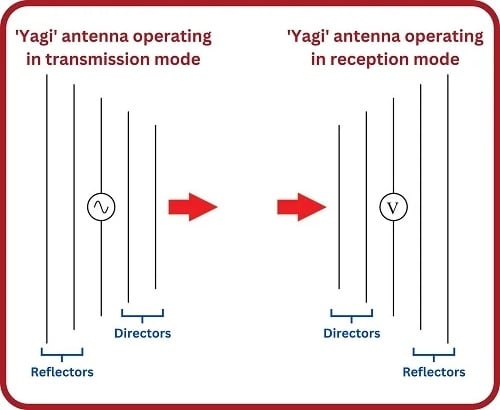
A simple yet highly effective antenna design for directional transmission and reception is the Yagi, named after its inventor. A Yagi is based on a half-wave dipole element surrounded by one or more wires longer than \(\lambda/2\) to the rear (called “reflectors”) and one or more wires shorter than \(\lambda/2\) to the front (called “directors”). The terms “reflector” and “director” are quite apt, describing their interaction with electromagnetic waves from the perspective of the dipole: reflectors reflect the waves, while directors direct the waves. The result is an antenna array that is much more directional than a simple dipole:

An example of a Yagi antenna used as part of a SCADA system is shown in this photograph, the antenna of course being the multi-element array in the upper-right corner:

Another example of a highly directional antenna design is the parabolic dish, often used in microwave and satellite communications. This photograph shows two “dish” antennas, one open to the weather (right) and the other covered with a weather-proof diaphragm to keep the antenna elements protected (left):

Some dish antennas use mesh or metal-tube reflectors rather than a solid parabolic reflector, as is the case in this next photograph:

REVIEW:
-
Tank circuits, or resonant circuits, convert a DC source into (ideally) a continuously oscillating output wave. Realistically, the oscillation decreases with time.
-
Antennas are designed to oscillate at particular frequencies, or multiples of that frequency.
-
As antenna length increases, the fundamental frequency decreases, leading to a rigorous science around antenna design.
-
Half-wave, quarter-wave, and yagi antennas remain among the most common antennas for radio signals.

very well explained. googol . keep it up
Thank you so much :D
Thanks to you, I now have a proper understanding of the basic mechanism of RF transmission !
That’s a pretty important thing for a newly licensed ham.
James - KI5SMN 73!
Written in an unusually clear manner. Chapeau!