 Facebook
 Google
 GitHub
 Linkedin
Memory Maps and I/O Addressing

Logic programming for PLCs begins with understanding the input, output, and internal (binary, integer, timer, and counter) memory addressing structures.
A wise PLC programmer once told me that the first thing any aspiring programmer should learn about the PLC they intend to program is how the digital memory of that PLC is organized. This is sage advice for any programmer, especially on systems where memory is limited, and/or where I/O has a fixed association with certain locations in the system’s memory. Virtually every microprocessor-based control system comes with a published memory map showing the organization of its limited memory: how much is available for certain functions, which addresses are linked to which I/O points, how different locations in memory are to be referenced by the programmer.
Discrete input and output channels on a PLC correspond to individual bits in the PLC’s memory array. Similarly, analog input and output channels on a PLC correspond to multi-bit words (contiguous blocks of bits) in the PLC’s memory. The association between I/O points and memory locations is by no means standardized between different PLC manufacturers, or even between different PLC models designed by the same manufacturer. This makes it difficult to write a general tutorial on PLC addressing, and so my ultimate advice is to consult the engineering references for the PLC system you intend to program.
Different generations and brands of PLCs adopt different styles of addressing, and it is helpful to explore many of these methods so that you can become more familiar with a style suited to your own programming environment.
-
Allen-Bradley (Rockwell) PLC-5, SLC 500, and MicroLogix 1000/1100/1400
-
Allen-Bradley (Rockwell) ControlLogix and CompactLogix
-
Siemens S7-1200
Allen-Bradley (Rockwell) Address-Based Programming
One of the most common brands of PLC in use in the United States is Allen-Bradley (Rockwell), which happens to use a unique form of I/O addressing students tend to find confusing. For these two reasons (popularity and confusion), I will focus on Allen-Bradley addressing conventions for the bulk of this section.
The following table shows a partial memory map for an Allen-Bradley SLC 500 PLC:
| File number | File type | Logical address range |
|---|---|---|
| 0 | Output image | \(\texttt{O:0}~to~\texttt{O:30}\) |
| 1 | Input image | \(\texttt{I:0}~to~\texttt{I:30}\) |
| 2 | Status | \(\texttt{S:0}~to~\texttt{S:15-163}~CPU~rev\) |
| 3 | Binary | \(\texttt{B3:0}~to~\texttt{B3:255}\) |
| 4 | Timers | \(\texttt{T4:0}~to~\texttt{T4:255}\) |
| 5 | Counters | \(\texttt{C5:0}~to~\texttt{C5:255}\) |
| 6 | Control | \(\texttt{R6:0}~to~\texttt{R6:255}\) |
| 7 | Integer | \(\texttt{N7:0}~to~\texttt{N7:255}\) |
| 8 | Floating-point | \(\texttt{F8:0}~to~\texttt{F8:255}\) |
| 9 | Network | \(\texttt{x9:0}~to~\texttt{x9:255}\) |
| 10 through 255 | User-defined | \(\texttt{x10:0}~to~\texttt{x255:255}\) |
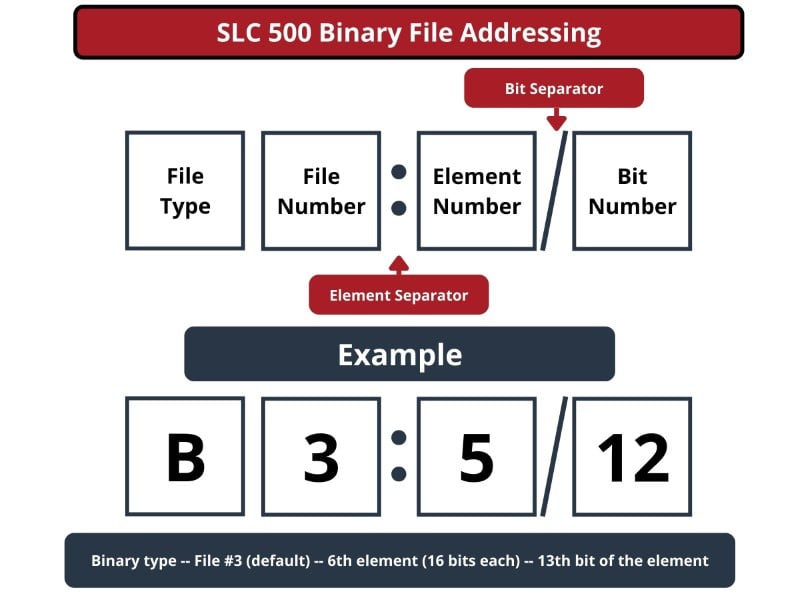
Note that Allen-Bradley’s use of the word “file” differs from personal computer parlance. In the SLC 500 controller, a “file” is a block of random-access memory used to store a particular type of data. By contrast, a “file” in a personal computer is a contiguous collection of data bits with collective meaning (e.g. a word processing file or a spreadsheet file), usually stored on the computer’s hard disk drive. Within each of the Allen-Bradley PLC’s “files” are multiple “elements,” each element consisting of a set of bits (8, 16, 24, or 32) representing data. Elements are addressed by number following the colon after the file designator, and individual bits within each element addressed by a number following a slash mark. For example, the first bit (bit 0) of the second element in file 3 (Binary) would be addressed as B3:2/0.
In Allen-Bradley PLCs such as the SLC 500 and PLC-5 models, files 0, 1, and 2 are exclusively reserved for discrete outputs, discrete inputs, and status bits, respectively. Thus, the letter designators O, I, and S (file types) are redundant to the numbers 0, 1, and 2 (file numbers). Other file types such as B (binary), T (timers), C (counters), and others have their own default file numbers (3, 4, and 5, respectively), but may also be used in some of the user-defined file numbers (10 and above). For example, file 7 in an Allen-Bradley controller is reserved for data of the “integer” type (N), but integer data may also be stored in any file numbered 10 or greater at the user’s discretion. Thus, file numbers and file type letters for data types other than output (O), input (I), and status (S) always appear together. You would not typically see an integer word addressed as N:30 (integer word 30 in the PLC’s memory) for example, but rather as N7:30 (integer word 30 in file 7 of the PLC’s memory) to distinguish it from another integer word 30’s that may exist in other files of the PLC’s memory.
This file-based addressing notation bears further explanation. When an address appears in a PLC program, special characters are used to separate (or “delimit”) different fields from each other. The general scheme for Allen-Bradley SLC 500 input and output terminal addresses is shown here:

Not all addresses refer the PLC to external, physical screw terminals attached to real-world I/O devices. Many individual memory bits are available in the PLC's memory - far more convenient in many cases that forcing the logic to consume all the available I/O points. For these binary bits of data, a very similar address structure is used, except this structure will not refer to physical slots or terminals, but rather files and elements.
In the following breakdown, a file can be specified for all of the internal memory types. The default fils for binary memory is file #3, but files 9 through 255 can be configured for the user's own needs.
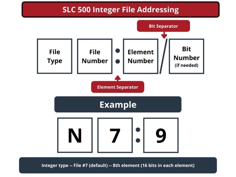
Not all file types need to distinguish individual words and bits. Integer files (N), for example, consist of one 16-bit word for each element. For instance, N7:9 it would be the 16-bit integer word number nine held in file seven. A discrete input file type (I), though, needs to be addressed as individual bits because each separate I/O point refers to a single bit. Thus, I:3/7 would be bit number seven residing in input element three. The “slash” symbol is necessary when addressing discrete I/O bits because we do not wish to refer to all sixteen bits in a word when we just mean a single input or output point on the PLC. Integer numbers, by contrast, are collections of 16 bits each in the SLC 500 memory map, and so are usually addressed as entire words rather than bit-by-bit.
As with the binary data, a default file is allocated for each memory type by default. There are 9 total default files, 0 through 8. The following files, from 9 all the way to file 255 are not allocated to any one specific purpose - the user can provide more allowance for extra bits, integers, or timers, however the project dictates.
| File Type | File Number |
|---|---|
| Output | 0 |
| Input | 1 |
| Status | 2 |
| Binary | 3 |
| Timer | 4 |
| Counter | 5 |
| Control Data | 6 |
| Integer | 7 |
| Float | 8 |
Certain file types in this list, such as timers, are more complex. Each timer “element” consists of two different 16-bit words (one for the timer’s accumulated value, the other for the timer’s target value) in addition to no less than three bits declaring the status of the timer (an “Enabled” bit, a “Timing” bit, and a “Done” bit). Thus, we must make use of both the decimal-point and slash separator symbols when referring to data within a timer. Suppose we declared a timer in our PLC program with the address T4:2, which would be timer number two contained in timer file four. If we wished to address that timer’s current value, we would do so as T4:2.ACC (the “Accumulator” word of timer number two in file four). The “Done” bit of that same timer would be addressed as T4:2/DN (the “Done” bit of timer number two in file four).
A hallmark of the SLC 500’s addressing scheme common to many legacy PLC systems is that the address labels for input and output bits explicitly reference the physical locations of the I/O channels. For instance, if an 8-channel discrete input card were plugged into slot 4 of an Allen-Bradley SLC 500 PLC, and you wished to specify the second bit (bit 1 out of a 0 to 7 range), you would address it with the following label: I:4/1. Addressing the seventh bit (bit number 6) on a discrete output card plugged into slot 3 would require the label O:3/6. In either case, the numerical structure of that label tells you exactly where the real-world input signal connects to the PLC.
To illustrate the relationship between physical I/O and bits in the PLC’s memory, consider this example of an Allen-Bradley SLC 500 PLC, showing two of its discrete input channels energized (indicated here are simple closed button electrical symbols, but they may be switches or sensors):

If an input or output card possesses more than 16 bits – as in the case of the 32-bit discrete output card shown in slot 3 of the example SLC 500 rack – the addressing scheme further subdivides each element into words and bits (each “word” being 16 bits in length). Thus, the address for bit numbers 18 and 21 of a 32-bit input module plugged into slot 1 would be I:1.1/2 and I:1.1/5 (since bit 18 is equivalent to bit 2 of word 1 – word 0 addressing bits 0 through 15 and word 1 addressing bits 16 through 31. Similar for bit 21.):

A close-up photograph of a 32-bit DC input card for an Allen-Bradley SLC 500 PLC system shows this multi-word addressing:
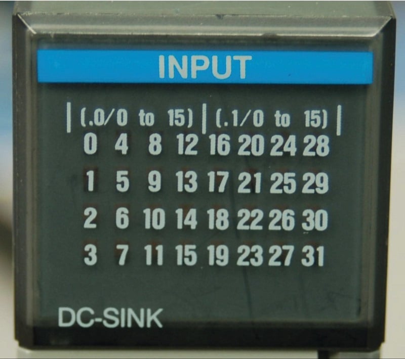
The first sixteen input points on this card (the left-hand LED group numbered 0 through 15) are addressed I:X.0/0 through I:X.0/15, with “X” referring to the slot number the card is plugged into. The next sixteen input points (the right-hand LED group numbered 16 through 31) are addressed I:X.1/0 through I:X.1/15.
Legacy PLC systems typically reference each one of the I/O channels by labels such as “I:1/3” (or equivalent) indicating the actual location of the input channel terminal on the PLC unit. The IEC 61131-3 programming standard refers to this channel-based addressing of I/O data points as direct addressing. A synonym for direct addressing is absolute addressing.
Addressing I/O bits directly by their card, slot, and/or terminal labels may seem simple and elegant, but it becomes very cumbersome for large PLC systems and complex programs. Every time a technician or programmer views the program, they must “translate” each of these I/O labels to some real-world device (e.g. “Input I:1/3 is actually the Start pushbutton for the middle tank mixer motor”) in order to understand the function of that bit. A later effort to enhance the clarity of PLC programming was the concept of addressing variables in a PLC’s memory by arbitrary names rather than fixed codes. The IEC 61131-3 programming standard refers to this as symbolic addressing in contrast to “direct” (channel-based) addressing, allowing programmers arbitrarily name I/O channels in ways that are meaningful to the system as a whole. To use our simple motor “Start” switch example, it is now possible for the programmer to designate input I:1/3 (an example of a direct address) as “Motor_start_switch” (an example of a symbolic address) within the program, thus greatly enhancing the readability of the PLC program. Initial implementations of this concept maintained direct addresses for I/O data points, with symbolic names appearing as supplements to the absolute addresses.
The modern trend in PLC addressing is to avoid the use of direct addresses such as I:1/3 altogether, so they do not appear anywhere in the programming code. The Allen-Bradley “Logix” series of programmable logic controllers is the most prominent example of this new convention at the time of this writing. Each I/O point, regardless of type or physical location, is assigned a tag name that is meaningful in a real-world sense, and these tag names (or symbols as they are alternatively called) are referenced to absolute I/O channel locations by a database file. An important requirement of tag names is that they contain no space characters between words (e.g. instead of “Motor start switch”, a tag name should use hyphens or underscore marks as spacing characters: “Motor_start_switch”), since spaces are generally assumed by computer programming languages to be delimiters (separators between different variables).
Having introduced Allen-Bradley’s addressing notation for SLC 500 model PLCs, I will now abandon it in favor of the modern convention of symbolic addressing throughout the rest of this chapter, so as to avoid making the programming examples brand- or model-specific. Each data point within my PLC programs will bear its own tag name rather than a direct (channel-based) address label.
Allen-Bradley (Rockwell) Tag-Based Programming
Tags are becoming the modern standard for assigning a memory address to a more logical, understandable text-based name assignment. This is not because memory allocation addressing is inefficient or ineffective. Rather, this change comes out of the recognition that the end goal of programming is to quickly create a program that performs a task, and provides as much information to future troubleshooting technicians as possible.
Because of this mindset, the model of determining the internal location of file, element, and bit numbers creates added time expense. If not documented properly, can also add a great deal of confusion.
Using tags to define memory locations is not a fundamentally different process than the addresses themselves. Indeed, the programmer must still be able to identify a single I/O terminal in order to program the PLC.
The main difference is a layer of isolation between the file addresses and the end user. In a tag-based system, a programmer defines a new piece of memory, based a program requirement, but can simply create the new tag without any knowledge of where it resides in the internal file structure.
Assume for example that a user must create a new timer to measure the duration of a heating process. In a file-based addressing system as before, the programmer chooses T4 (the timer file) and selects the next available timer, perhaps timer number 7.
The program can now be written with T4:7.PRE for the preset value, and if needed, can select a single bit out of that preset value with the address T4:7.PRE/2.
In an alternative tag-based environment, the pre-defined files do not exist from the factory. The programmer simply opens a tag database and creates a new tag with a data type of ‘Timer’. This automatically generates a new allocation of several tags associated with the timer, and assigns the memory required to store all the associated values.
The discussion then becomes: what sorts of data types are allowable in this new tag-based environment?
As before, the most basic ‘atomic’ data types are only binary, integer, float, and string (text/character) values. Most modern PLCs are established with 32-bit CPU architecture, so the 16-bit word from previous generations is now largely replaced with the 32-bit double word as the basic memory storage size.
| Data Type | Alternative Name(s) | Number of Bits |
|---|---|---|
| Boolean | BOOL, bit | 1 |
| Short Integer | SINT, short, sword | 8 |
| Integer | INT, word | 16 |
| Double Integer | DINT, double, double word, dword | 32 |
| Float | REAL | 32 |
| String | 8 per character |
All other data types become structured combinations of these basic types. Timers, counters, and even I/O modules become structures of basic atomic data types.
ControlLogix and CompactLogix I/O Addresses
All I/O terminals must still be identified by an address that points to their physical location with respect to the CPU, but these are different from the file, element, and bit pointers of the older systems.
These addresses still act as a ‘map’ of sorts, which can direct a technician to the exact spot where any screw terminal may be found. The structure appears in the image below, along with an example.
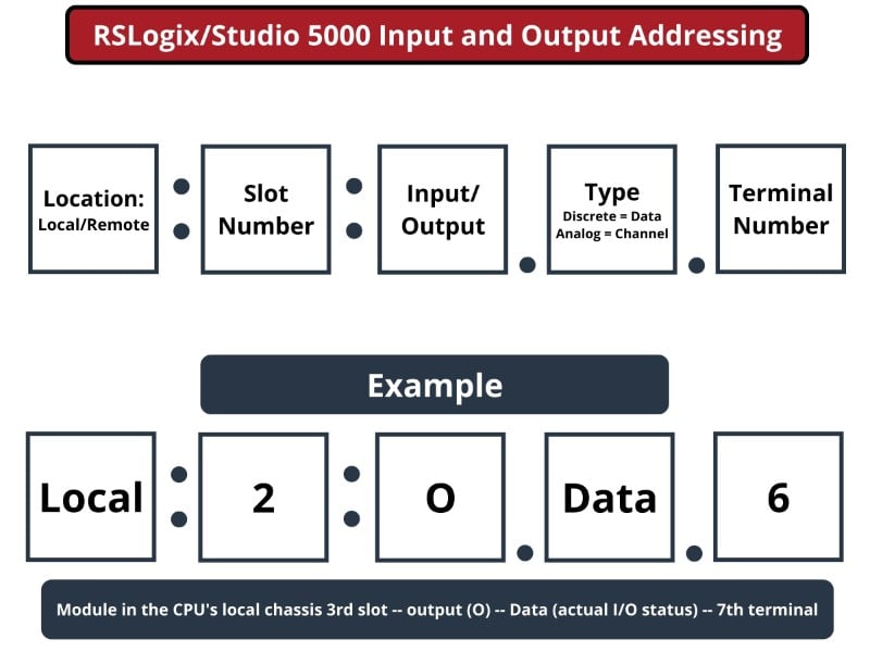
The structure begins by pointing to either a local or remote chassis. When any external chassis (such as another PLC, or a remote I/O rack) is added to the project, it is given a name. If the I/O terminal is located in the remote rack, the address will begin with the name of the remote rack, not with the word Local which is reserved only for the CPU’s local chassis.
The slot number in the local or remote chassis is the next address number, always starting with slot #0. Often, the CPU is placed in slot #0, but this should not always assumed to be the case. Input and output terminals are indicated with I and O respectively. Configuration and status data may also be added into certain module types, so C and S may also appear in the address.
The type component refers to the module being used. The reference to ‘data’ in an address points to the on/off status of a single discrete terminal, identified by the bit number. In an analog system, a single terminal represents a channel, so in those cases, the word ‘channel’ will be followed by the terminal number.
When any new I/O module is added to a project, a new double integer (DINT) set of memory addresses is reserved for that module. With 32 bits of availability, every module is now a new assignment of 32 new bits as the input register. Even if the module only has 16 terminals to monitor, 32 bits will still be consumed.
Sometimes, these 32 bits can be used advantageously.
For example, assume a new project is created and a variable frequency motor control device (VFD) is added.
A set of command words will be sent and received from this VFD. The PLC will store the outgoing data as a 32-bit double word register, but the VFD may be able to split this into two 16-bit words. One word may store all of the start/stop/jog/direction commands, while the second word contains the integer value representing the desired operating speed of the motor.
So while the PLC consumes only a single 32-bit address for the information, it may serve two or more purposes when split apart (called ‘parsing’) by a receiving device.
Memory Organization
This tag-based addressing structure presents a new challenge, but overcomes it with a significant advantage.
First, the new challenge is a lack of organization of memory allocation when compared to pre-defined allocation from before. All of the timers would reside in the same contiguous location on the drive, as would all other files. This increased the speed of retrieval for relatively slow processors of old. In this new method, each new data tag consumes an address, creating a virtual dart-board of locations.
For example, assume an emergency stop button tag is created for a new machine program and placed in the ladder logic. Then, many months later, a second E-stop button is added, the tag is created, and then inserted into the program. Although these two binary bits have a nearly identical purpose, and may be located close to each other in reality, the pointer addresses may be far removed on the storage drive. Advancements in solid-state data storage reduce the time required to retrieve data.
The benefit that overcomes this challenge becomes apparent in the far more efficient use of critical memory in the CPU. If a program only needs a timer or two, the entire Timer file T4 is not pre-defined for that use. The same is true for counters, integers, floats, and even I/O modules.
Today’s PLC programs are as diverse as the projects they support, so it is more important to allow programmers to define their own requirements - not have limits set by the manufacturers.
Although the programmer is free to create new tags, the addresses still exist at the base layer of the PLC. Every data type is still created and stored with a unique address pointer as in all legacy PLCs. The only difference is the luxury of not needing to know where each existing and new integer or bit is stored when you are hard at work fixing a program under pressure.
Siemens S7 Data Address Programming
Another popular style of tag-based programming is used in the Siemens S7 PLC series (including the S7-300, 400, 1200, and 1500). These are programmed using the Totally Integrated Automation TIA portal software.
In this system, each tag is created by name, and then assigned an address based on available memory locations. All inputs, outputs, and memory locations are directed to 8-bit byte of 16-bit word registers, and there will likely be several thousand of these registers, depending on the specific PLC’s memory.
Each register can be referenced as an entire byte or integer, or two registers may be referenced as a 32-bit integer, or finally, a single bit from a register can be retrieved. In this way, every data type from boolean to integers to floats can be created and stored, but must be assigned a memory location.
In these PLCs, each I/O module, or embedded set of I/O terminals is already linked to a particular set of registers. Discrete and analog terminals will be pre-determined and must be retrieved from the documentation.
For example, an S7-1214C AC/DC/Rly has 14 discrete inputs, 10 relay outputs, and 2 analog inputs. This model is equipped with a removable signal board providing 1 additional analog output. Each of these signals is already located in a particular memory address within the controller.
The discrete input and output registers are read as 8-bit bytes, so each byte can store 8 input or output terminals. Since there are 14 inputs, two bytes are required. If you wish to read any of the input terminals, you would use the tag addresses I0.0 to I0.7 for the first 8 terminals, then I1.0 to I1.5 for the remaining 6.
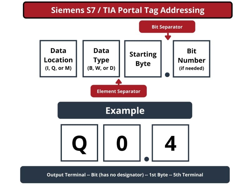
In a similar vein, the 10 output terminals would be addressed as Q0.0 to Q0.7 for the first 8 terminals, then Q1.0 to Q1.1 for the remaining 2.
This PLC has two analog input terminals. Since they are not single-bit values, they must be referenced as 16-bit words. Since the memory is divided into bytes, it takes two consecutive bytes to store a single word. This is accomplished by using an address with an Input structure (I), indicating it as a word (W), and being sure to only use every other byte address.
By default (although the user has some ability to re-map tags) the locations in the PLC’s memory for these analog inputs use the following addresses:
First analog input, labeled as AI 0 on the PLC: IW64
Second analog input, labeled as AI 1 on the PLC: IW66
Memory addresses can be placed at the user’s discretion since they are not tied to physical I/O registers. When defining a new tag, start by selecting M (for memory storage). If the tag must be a single bit, the structure may be M4.1 for example, the second bit of the 5th byte.
If the tag must be an entire byte, the tag would be MB4 and the next one would be MB5. As the integer size increases, such as a word, MW4 may be the first tag, but MW6 must be the next one, since a 16-bit word consumes two consecutive bytes. A double word is twice the size of a word, so MD4 must be followed by MD8.
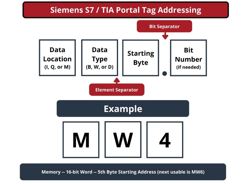
Floating point, or ‘real’ values use the same number of bits as a double word, so a tag to store a float value would also be MDxy, with xy being the starting byte of the next 4 consecutive addresses.
Tag Database Management
With this comparison of tags and addresses in the rear-view mirror, it is worth discussing the process of tag creation, and learning how to manage sets of tags in a database.
A tag database is the logical organization of labels for the data used in a program. It is not classified in order of where the data is stored in the memory of the controller, in contrast to an address-based memory table. Storage files are not in order, but rather the labels can be sorted alphabetically, by order of creation, or by data type. This allows programmers to treat the memory storage in their PLC much more like any traditional database.
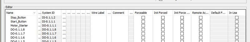
Inside this database, tags can be viewed and created when needed. Often, the current value of a tag can be monitored while the program and I/O registers are actively scanning. When a tag is created by selecting a unique name and data type, that unique pointer address can still be accessed. Commonly, this is used to link tags to human-machine interface (HMI) tag lists, although there are a wide variety of HMI programming strategies.
Several critical tag components should be considered in the database. In most programming software interfaces, each of the following details can be shown or hidden in the ladder rungs to display valuable information as needed.
Tag Name
Logical names will be the first visible element when troubleshooting the running ladder logic, so it’s important to consider the names as they would appear in the code, and in the database. If the database arranges the tags alphabetically, consider stating each group of like items with the same character so they remain readable, yet grouped in the database.
Many languages do not support spaces (the space character) in a tag name, so it can be a good practice to use alternative methods like underscores, mixed-case capital and lowercase letters, and other strategies to name tag.
Wire Label
A wiring label is the short code that will appear on a physical wire in a control cabinet, and in a schematic ‘wire’ line connecting two components. It may also be a reference to a line in a printed version of the program.
Proper wire labels attached to the tags in the database can aid the troubleshooter in tracing a circuit from the PLC terminal back to the original field device - switch, sensor, or coil - that may be a suspect in a faulty system.
Description
A tag description can provide further information about the function and use of a tag, even if it does not directly reference a physical I/O terminal. A timer, for example, may be used to treat a chemical batch process, but the duration of the timer is dependent on several factors from other inputs. A description can be a helpful method of noting these important details that can aid a future troubleshooting or process improvement upgrade.
Another benefit of a description field for a physical I/O device is to contain details about the component - specifications, part numbers, and even hyperlinks to datasheets. This can save valuable time when the most likely suspect is a faulty part that needs replacement. If the program already contains the details of the part, a replacement can be immediately retrieved rather than the typical process of removing the bad part, locating the replacement from a supply room, then reinstalling the new part.
REVIEW:
-
Address-based memory points the programmer to the location of pre-assigned files, elements, and bits that correspond to each piece of data.
-
Tags allow programmers to assign logical names while the program still assigns the addresses and pointers in the background.
-
Some software allows the creation of tags on demand as needed, but still allows a programmer to have full control over where the address is located in the memory array.
