 Facebook
 Google
 GitHub
 Linkedin
Pilot Valves and Pneumatic Amplifying Relays
Self-balancing mechanisms consisting solely of a baffle/nozzle detector coupled to a feedback bellows, while functional, are not always practical as field instruments. Nozzles and orifices must be made rather small in diameter in order to minimize compressed air usage, but this means the mechanism will require significant time to alter its output pressure (i.e. to fill and empty the bellows and associated air tubing). Such a pneumatic mechanism will be impractically slow if connected to a remote indicating instrument through a long run of tubing, owing to the relatively large volume of that tube.
A practical solution to the compromise between air consumption and responsiveness inherent to simple baffle/nozzle/bellows mechanisms is to boost the nozzle backpressure (and volume) using a pneumatic “amplifier” device. With a pneumatic amplifier in place, the detector (baffle/nozzle) need not leak great quantities of compressed air, since the amplifier will provide the volume boost necessary to quickly fill (and vent) the bellows and signal tubing.
The design challenge for us, then, is how to construct such a pneumatic amplifier: a mechanism to amplify small pneumatic signal changes into larger pneumatic signal changes. In essence, we need to find a pneumatic equivalent of the electronic transistor: a device that lets a small signal control a larger signal.
First, let us analyze the following pneumatic mechanism and its electrical analogue (as shown on the right):

As the control rod is moved up and down by an outside force, the distance between the plug and the seat changes. This changes the amount of resistance experienced by the escaping air, thus causing the pressure gauge to register varying amounts of pressure. Moving the control rod up opens the variable restriction formed by the plug and seat, venting air more easily and decreasing the output pressure. Moving the control rod down closes off the vent, causing output pressure to rise. These up-and-down rod motions are analogous to the variable resistor decreasing and increasing resistance, respectively, causing the output voltage to change in direct relation to the variable resistance.
There is little functional difference between this mechanism and a baffle/nozzle mechanism. Both work on the principle of one variable restriction and one fixed restriction (the orifice) “dividing” the pressure of the compressed air source to some lesser value.
The sensitivity of this pneumatic mechanism may be improved by extending the control rod and adding a second plug/seat assembly. The resulting mechanism, with dual plugs and seats, is known as a pneumatic pilot valve. An illustration of a pilot valve is shown here, along with its electrical analogue (on the right):
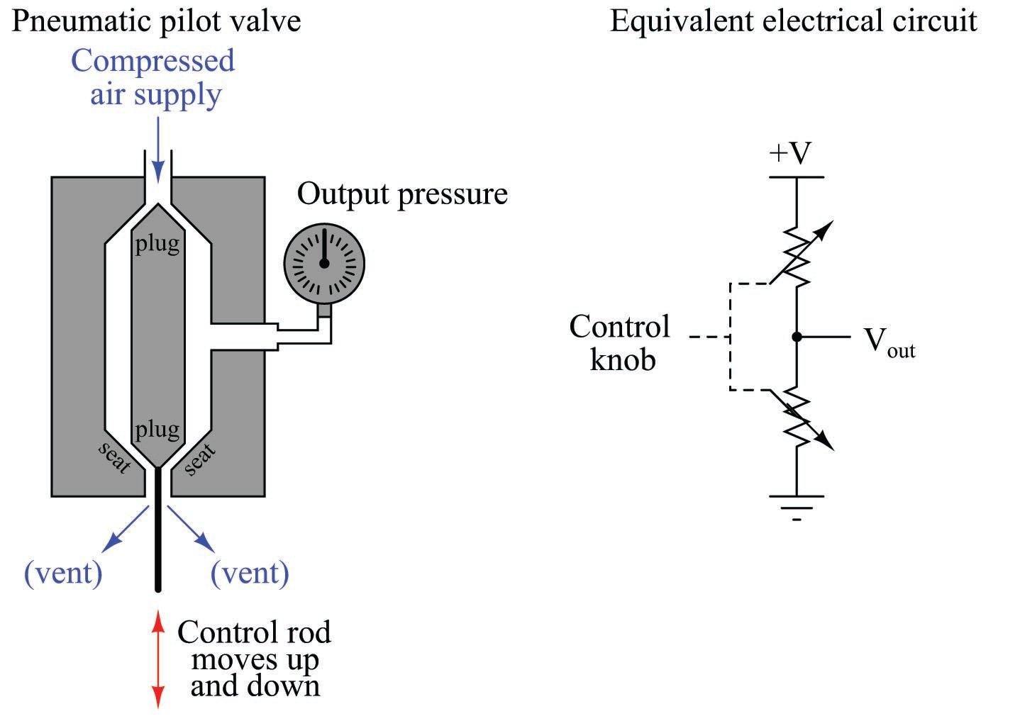
As the control rod is moved up and down, both variable restrictions change in complementary fashion. As the control rod moves up, the upper restriction closes off (restricting supply air) while the lower restriction opens up (venting more), causing the output pressure signal to decrease. As the rod moves down, the upper restriction opens (allowing more supply air in) and the lower restriction closes off (venting less), causing the output pressure to rise. The combination of two restrictions changing in opposite direction results in a much more aggressive change in output pressure for a given amount of rod motion than the previous mechanism with its fixed restriction and single variable restriction.
A similar design of pilot valve reverses the directions of the two plugs and seats. The only operational difference between this pilot valve and the previous design is an inverse relationship between control rod motion and pressure:

Now, moving the control rod up increases pressure while moving it down decreases pressure: precisely opposite the action of the previous pilot valve.
At this point, all we’ve managed to accomplish is build a better baffle/nozzle mechanism. We still do not yet have a pneumatic equivalent of an electronic transistor. To accomplish that, we must have some way of allowing an air pressure signal to control the motion of a pilot valve’s control rod.
If we add a diaphragm to the pilot mechanism, we will create a proper pneumatic relay. The following relay and its electronic analogue are shown here:

The diaphragm is nothing more than a thin disk of sheet metal, upon which an incoming air pressure signal presses. Force on the diaphragm is a simple function of signal pressure (\(P\)) and diaphragm area (\(A\)), as described by the standard force-pressure-area equation:
\[F = PA\]
If the diaphragm is taut, the elasticity of the metal allows it to also function as a spring. This allows the force to translate into displacement (motion), forming a definite relationship between applied air pressure and control rod position. Thus, the applied air pressure input will exert control over the output pressure.
It is easy to see how the input air signal exerts control over the output air signal in these two illustrations:

Since there is a direct relationship between input pressure and output pressure in this pneumatic relay, we classify it as a direct-acting relay. If we were to add an actuating diaphragm to the first pilot valve design, we would have a reverse-acting relay as shown here:

The gain (\(A\)) of any pneumatic relay is defined just the same as the gain of any electronic amplifier circuit, the ratio of output change to input change:
\[A = {\Delta \hbox{Output} \over \Delta \hbox{Input}}\]
For example, if an input pressure change of \(\Delta\)2 PSI results in an output pressure change of \(\Delta\)12.9 PSI, the gain of the pneumatic relay is 6.45.
Whether or not a pneumatic relay provides a pressure gain, it is guaranteed to provide a volume gain which is necessary to make pneumatic field instruments practical. Note how the diaphragm chamber where the input pressure goes is sealed off: this means there will be no continual draw (or leakage) of input signal air volume. Any pneumatic sensing element sending a pressure signal to the input of a pneumatic relay will not be “loaded” by the relay. The relay, on the other hand, is able to supply or vent a continual flow of air at its output port as needed. Just as a transistor amplifier circuit presents a light load to the input signal and a comparatively “heavy” source/sink capacity to any load connecting to its output terminals, pneumatic relays similarly boost the volume capacity of a pneumatic signal. Recall that this was precisely our goal for increasing the responsiveness of a baffle/nozzle mechanism: to have a pneumatic amplifier capable of boosting the nozzle’s backpressure signal.
Adding a pneumatic pressure-amplifying relay to a force-balance system such as our hypothetical laboratory scale improves the performance of that pneumatic system in multiple ways:

The pressure gain of the pneumatic amplifying relay makes the force-balancing bellows respond more aggressively to changes in baffle position than it could on its own. This makes the scale more sensitive, better able to sense small changes in applied weight.
The volume gain of the pneumatic amplifying relay results in greatly decreased response time to changes in applied weight. Without a relay in the system, the rate at which the force-balance bellows fills and empties with compressed air is a direct function of the orifice’s and nozzle’s restrictiveness, respectively. Nozzles and orifices designed for high restriction (small diameters) work well to conserve air usage over time, but they also limit the rate of air flow in or out of the feedback bellows. With an amplifying relay in place, however, we get the best of both worlds: the nozzle and orifice bores may be minimized for minimum air consumption, while the relay’s valves may be made large enough to ensure high flow capacity to and from the bellows for quick response.
It should be noted that the principles of self-balancing mechanisms, baffles and nozzles, amplifying relays, and the like are not limited to pneumatic systems. It is also possible to build self-balancing hydraulic systems using all the same principles, the only difference being the use of liquid (oil) as the working fluid instead of gas (air). An example of a force-balance hydraulic system is the ASCO model NH90 “Hydramotor” linear actuator, which uses a self-contained hydraulic pump and reservoir to provide pressurized oil for the mechanism, a baffle/nozzle mechanism to detect out-of-balance conditions, and a hydraulic amplifying relay to boost the nozzle backpressure signal to perform useful work through a hydraulic actuating cylinder.
The Foxboro corporation designed a great many of their pneumatic instruments using just one style of (highly sensitive) amplifying relay:

The motion of the diaphragm actuates a pair of valves: one with a cone-shaped plug and the other with a metal ball for a plug. The ball-plug admits supply air to the output port, while the cone-shaped “stem valve” plug vents excess air pressure to the vent port.
The following photograph shows one of these relay units:

Two slotted-drive screws attach the relay to the rest of the controller mechanism, while two smaller (Phillips-drive) screws hold the relay assembly together.
The Fisher corporation used a different style of amplifying relay in some of their legacy pneumatic instruments:

The following photograph shows one of these relay units (colored black) attached to the back of a model 546 I/P transducer (colored grey):

The pressure gain of this Fisher relay is much less than that of the Foxboro relay, since output pressure in the Fisher relay acts against input pressure by exerting force on a sizable diaphragm. The movable vent seat in the Fisher relay makes this design a “non-bleeding” type, meaning it possesses the ability to close both supply and vent valves at the same time, allowing it to hold an output air pressure between saturation limits without bleeding a substantial amount of compressed air to atmosphere through the vent. The Foxboro relay design, by contrast, is a “bleeding type,” whose ball and stem valves cannot close simultaneously, and thus always bleeds some compressed air to atmosphere so long as the output pressure remains somewhere between saturation limits.

Nice one