 Facebook
 Google
 GitHub
 Linkedin
Polyphase AC Power

Multiple phases can deliver more consistent, steady power than single phase
Three-phase AC power is the most common form of industrial voltage service. Polyphase power is produced and consumed with special attention devoted to balancing the various legs to preserve power quality.
“Polyphase” means “many phases,” describing a form of AC electrical system where multiple sinusoidal voltages exist that are not in step with each other. The most common form of polyphase AC power in industry is three-phase, but all polyphase systems share similar traits. A good way to understand three-phase AC systems is to begin with an understanding of simpler, single-phase systems.
Single Phase AC
A simple alternator (AC generator) is nothing more than a magnetized rotor spinning between a pair of electromagnetic poles, the stationary wire coils (“stator windings”) developing AC voltage as the spinning rotor’s magnet passes by:
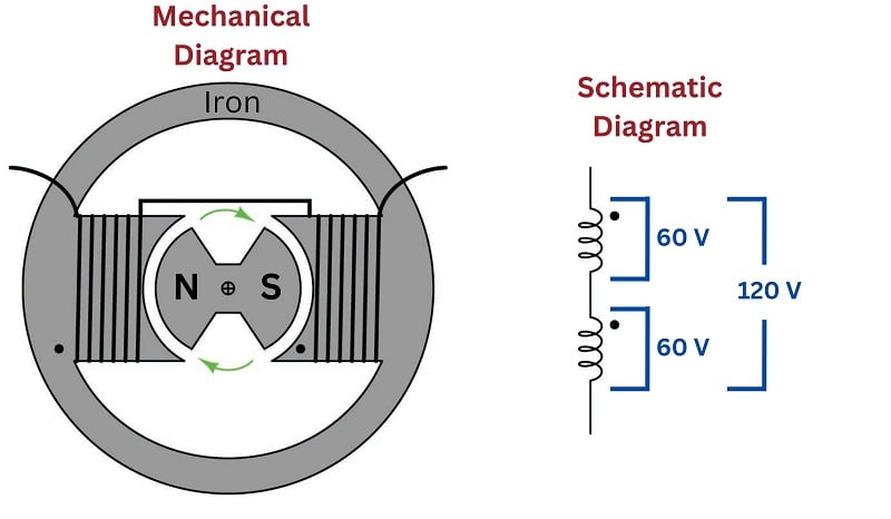
Note that the stator is comprised of two windings connected in series-aiding fashion, so that their respective AC voltages directly add. If each winding of this machine develops 60 volts, the series pair will develop 120 volts. This machine is properly called a single-phase alternator, because all its stator winding voltages are in-phase with each other.
Three Phase AC
A much more common alternator design uses three sets of stator poles, each one with its own winding pair, to generate three AC voltages phase-shifted from one another by 120\(^{o}\). The reason these three AC voltages are not in-phase with each other is precisely because the three stator poles are not physically aligned with each other, which means the magnetic poles of the spinning rotor will pass by each stator pole pair at different times:
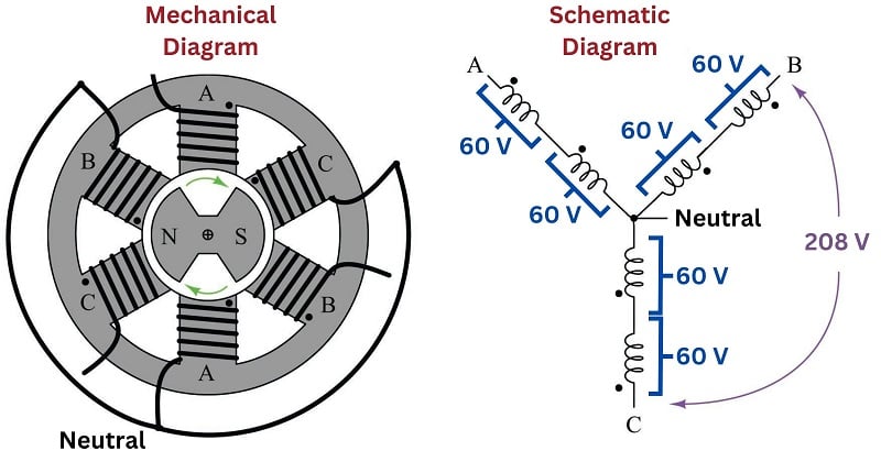
Note that each pair of stator winding voltages directly add, because they are in phase with each other. In the example shown, each individual stator winding develops 60 volts, with each series-aiding pair (each “phase” of the alternator) developing 120 volts. However, the voltage appearing between different stator winding pairs is neither the simple sum (\(120 + 120\)) nor the simple difference (\(120 - 120\)) of each phase voltage. Rather, the phase-to-phase voltage is the trigonometric sum of two phasor quantities, spaced 120\(^{o}\) apart. In the example shown, \(120 \angle 0^{o} + 120 \angle 120^{o} = 207.85 \angle 60^{o}\), which is approximately 208 volts. This machine is properly called a three-phase alternator. More specifically, this alternator is one with a wye-connected stator winding set, because the geometric configuration of the stator windings resembles that of the letter “Y”.
The following oscilloscope screenshot shows the output of a three-phase alternator, each channel of the oscilloscope connected across one phase of the alternator (e.g. Channel 1 across “A” and Neutral, Channel 2 across “B” and Neutral, and Channel 3 across “C” and Neutral):

Phase Shift and Phase Sequence
In this oscillograph image we can clearly see a 120\(^{o}\) phase shift between successive phase voltage waveforms. From this image we may also discern the phase sequence or phase rotation of the system: the sequential order in which the three phases reach their respective peak values. Phase sequence is determined by the direction of the alternator shaft’s rotation as well as the orientation of the stator phase windings. Surveying the three sine waves from left to right (the forward direction of time) on the oscillograph, we see channel 1 (Yellow) reaches its positive peak 120 degrees before channel 2 (Blue), which reaches its positive peak 120 degrees before channel 3 (Magenta). A common method of describing phase rotation is to list the phase letter labels in their order of sequence over time, in this case the triad ABC. It should be noted that a phase sequence of ABC is synonymous with BCA and also with CAB. This is easy to see if we write the letters in sequence for several rotations of the alternator, seeing that all three triads may be found within the longer sequence: ABCABCABCABC.
This trigonometric relationship between voltages in this “wye” connected alternator is clearly shown in the following phasor diagram. Solid phasors express the phase voltage for each of the three winding pairs in a three-phase alternator, while dashed lines express the line voltage between any two of the three output terminals on the alternator. The direction of each phasor expresses its phase shift in time, as the sine wave voltages produced by each of the three phase windings will be shifted apart from each other by 120 degrees. Here, each phase winding in the alternator happens to produce 120 VAC, resulting in a line voltage equal to the trigonometric sum of the 120 VAC phasors, 208 VAC:

A simple way to calculate the side lengths of these non-right triangles is to use the Law of Sines, which simply states the ratio between the length of a triangle’s side and the sine of its opposite angle is constant, for any triangle:
\[{\sin a \over A} = {\sin b \over B} = {\sin c \over C}\]
Applying this to the solution of the voltage between phases A and B (120 volts each, individually):
\[{\sin 120^{o} \over V_{AB}} = {\sin 30^{o} \over V_A} = {\sin 30^{o} \over V_B}\]
\[{\sin 120^{o} \over V_{AB}} = {\sin 30^{o} \over 120 \hbox{ volts}}\]
\[V_{AB} = (120 \hbox{ volts}) \left({\sin 120^{o} \over \sin 30^{o}}\right)\]
\[V_{AB} = 207.84 \hbox{ volts} \approx 208 \hbox{ volts}\]
The ratio \(\sin 120^o \over \sin 30^o\) is equal to the square-root of three (\(\sqrt{3}\)), and this factor frequently appears in three-phase electrical system calculations.
Some three-phase alternators have their phase windings connected differently, in a “delta” configuration rather than a “wye” configuration:

The phasor diagram for voltage in a delta-connected alternator is simpler, because phase voltage is exactly equal to line voltage, with each phase coil directly connected to a pair of line terminals:

The following photograph shows the terminal connections on the rear side of a three-phase alternator intended to provide electrical power on a heavy-duty truck or boat. Note the three power terminals at the bottom of the photograph (with yellow-colored wire connectors attached), where the three-phase AC power is output. Also note the two copper “slip rings” I am pointing to with my finger, where DC power is conducted through stationary carbon “brushes,” through the copper rings on the shaft, to a winding on the spinning rotor to control its magnetization. The shaft of this alternator, normally coupled to the crankshaft of the vehicle’s engine by a V-belt, is on the far side of the alternator hidden from view of the camera:

Larger alternator units, such as those found in power plants, do not differ substantially in design from this small unit. Sets of stator windings around the circumference of the machine connected in either a wye or a delta configuration generate three-phase AC power, while a magnetized rotor spins at the center of the machine providing the changing magnetic field necessary to induce voltage in those stator windings. Permanent-magnet rotors are seldom used because they offer no way to control or regulate the machine’s output voltage during operation. Instead, the rotor has a single winding of its own, energized by DC supplied externally by a voltage regulator circuit. If more AC voltage is desired from the alternator, the regulator circuit sends more direct current to the rotor in order to strengthen its magnetic field. If less AC voltage is desired, the regulator sends less current to the rotor’s winding in order to weaken its magnetic field.
Single Phase vs Three Phase AC Power
One of the advantages of three-phase AC power over single-phase AC power is a more constant delivery of electrical energy to the load over time. With three sets of stator windings at work, the combined effect is not unlike a triple bicycle with the three riders’ legs staggered by 120\(^{o}\) of rotation, or of a multi-cylinder automobile engine with the pistons staggered apart from each other: at any given time, at least one of the phases will be at or near its peak. Single-phase AC systems, by contrast, pulsate to a much greater extent.
In a single-phase AC circuit, energy transfer actually stops completely twice per cycle, when the current waveform passes through zero. This never happens in a polyphase system, because there are always other phases at non-zero current values when any one phase is at its zero-crossing point, owing to the fact that the phases in a polyphase power system are shifted from one another. This fact results in more efficient transfer of energy in AC power systems: a three-phase power system can actually transfer the same amount of power as a comparable single-phase power system using less metal in the power line conductors, despite the fact that a greater number of conductors is necessary (3 versus 2).
Another advantage of three-phase AC power is in applications where the AC is to be rectified into DC. The rectified output of a three-phase alternator is “smoother” than the rectified output of a single-phase alternator, with less ripple voltage to interfere with on-board electronic devices such as radios, because the phase-shifted currents overlap each other. This is why all automotive alternators are three-phase rather than single-phase machines.
A comparison of single-phase rectification versus three-phase rectification shows this clearly:
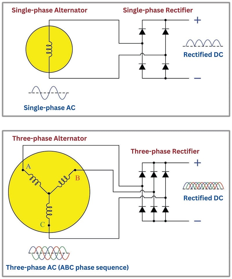
Not only is the ripple of the rectified DC voltage less in a three-phase system than in a single-phase system, but the frequency of that ripple is three times as great, making it easier to filter213 out of the DC power.
3 Phase Delta vs Wye Configuration
Two basic forms of three-phase sources and loads appearing in industrial power systems are the delta (\(\Delta\)) and the wye (or simply Y) configurations. A “wye-connected” device has its three elements joined at one common point in the middle as such:

By contrast, a “delta-connected” device has its three elements joined as the sides of a triangle:

Each configuration has its own unique advantages and disadvantages in the larger context of a three-phase electrical power system. Either source type may connect to either load type (e.g. delta to wye, delta to delta, wye to delta, wye to wye) so long as the voltage and current ratings of all components are compatible.
The voltage appearing across the terminals of each element in a polyphase device is called the phase voltage, and the current through each element in a polyphase device is called the phase current:

Voltage appearing between any two of the connecting conductors (power lines) is called the line voltage of the polyphase system, and current through any of the connecting conductors (power lines) is called the line current:
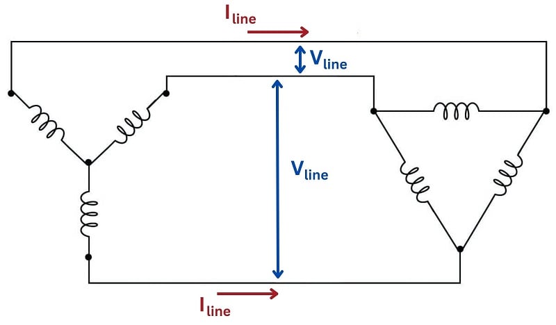
Line and phase quantities relate to each other differently between delta devices and wye devices. Line voltage for a balanced wye device exceeds phase voltage by a factor of \(\sqrt{3}\), while line current for a balanced delta device exceeds phase current by the same factor:
| System type | Voltage | Current |
|---|---|---|
| Wye (Y) | \[V_{line} = \sqrt{3} \times V_{phase}\] | \[I_{line} = I_{phase}\] |
| Delta (\(\Delta\)) | \[V_{line} = V_{phase}\] | \[I_{line} = \sqrt{3} \times I_{phase}\] |
While it may be tempting to simply memorize these mathematical relationships, it is far better to understand why they are so. In a wye-connected device, line current must be equal to phase current because each power line is in series with each (respective) phase element, and we know that series-connected elements must share the same current. Likewise, line voltage must be equal to phase voltage in a delta-connected device because each power line pair connects in parallel fashion to each (respective) phase element, and we know that parallel-connected elements always share the same voltage:

Phase and line voltages are unequal in wye-connected devices, as are phase and line currents in delta-connected devices. In each of these cases, though, we may see once again by visual inspection that these line and phase quantities cannot be equal because the line quantities are the result of two joining phase quantities. In a wye network, line voltage is the series (phasor) sum of two phase voltages. In a delta network, line current is the parallel (phasor) sum of two currents summing at a node. If we know the system in question is balanced, however, we may be assured that the multiplying factor between these line and phase quantities will be the square-root of three (\(\sqrt{3}\)), therefore line voltage is \(\sqrt{3}\) times greater than wye phase voltage, and line current is \(\sqrt{3}\) times greater than delta phase current:

As an example of phase and line voltages in a wye-connected system, we see a great many three-phase industrial power circuits in the United States of the “480/277” volt configuration. These are a wye-connected devices exhibiting having phase voltages of 277 volts (each) and a balanced line voltage of 480 volts.
In the wye-connected system we see how the two phase voltages add in series (indirectly) to form the larger line voltage. In the delta-connected system we see how the larger line current splits up in parallel branches (indirectly) to form two smaller phase currents. The key to understanding these mathematical relationships is to recognize where the rules of series and parallel connections dictate the quantities be identical or different, and then all we need to remember is that if the two are different, the line quantity will be greater by a factor of \(\sqrt{3}\).
Power in a Three Phase Circuit
Suppose we have a 480/277 wye-connected alternator supplying electrical power to a delta-connected load consisting of three 200 ohm resistive heating elements:

To begin our calculation of all electrical quantities in this circuit, we will apply Ohm’s Law to the calculation of phase current at the load, since we already know phase voltage (480 volts) and phase resistance (200 ohms) there:
\[I_{phase(load)} = {480 \hbox{ V} \over 200 \> \Omega} = 2.4 \hbox{ A}\]
Now that we know phase current at the delta-connected load, we may calculate line current for the whole system by multiplying by the square-root of three:
\[I_{line} = (\sqrt{3})(2.4 \hbox{ A}) = 4.157 \hbox{ A}\]
This line current must be the same as the phase current in the wye-connected alternator, since line and phase currents are equal in wye-connected devices by virtue of their series connection. We already know the phase voltage of the alternator (277 volts) because that was given to us, but we could just as well calculate it from the line voltage of 480 volts as such:
\[V_{line} = (\sqrt{3})(V_{phase(source)})\]
\[V_{phase(source)} = {V_{line} \over \sqrt{3}}\]
\[V_{phase(source)} = {480 \hbox{ V} \over \sqrt{3}} = 277.1 \hbox{ V} \approx 277 \hbox{ V}\]
Tabulating all phase voltages and currents in our balanced system with a line voltage of 480 V and a line current of 4.157 A:
| Quantity | Source | Load |
|---|---|---|
| $V_{phase}$ | 277 V | 480 V |
| $I_{phase}$ | 4.157 A | 2.4 A |
Power for each of the three source or three load elements in this balanced system is simply the product of phase voltage and phase current (\(P = IV\)) because voltage and current are in-phase at each of the individual resistors. Expanding our table to include the power for each phase element:
| Quantity | Source | Load |
|---|---|---|
| $V_{phase}$ | 277 V | 480 V |
| $I_{phase}$ | 4.157 A | 2.4 A |
| $P_{phase}$ | 1152 W | 1152 W |
Total generated power at the alternator (as well as total dissipated power at the resistive heater) is the simple sum of all three phase elements: 3456 watts in each case. No “square-root-of-three” factor is required in this calculation, because power (work over time) is not a phasor quantity. The Law of Energy Conservation demands that all power be accounted for, and thus three resistors dissipating 1152 watts each must be together dissipating 3456 watts total:

In the interest of convenience, though, it is helpful to have a formula to calculate power in a balanced three-phase system knowing just the line voltage and current rather than phase voltages and currents. You will note how the simple product of line voltage (480 V) and line current (4.157 A) does not yield total power (3456 W) in this system. We may develop a proper formula for calculating total power from line voltage and current by beginning with the formula described in calculating total power from the power of each resistor at the delta-connected load:
\[P_{total} = (3) (P_{phase})\]
\[P_{total} = (3) (I_{phase})(V_{phase})\]
We may substitute \(I_{line}\) for \(I_{phase}\) and \(V_{line}\) for \(V_{phase}\) in this equation if we properly relate them for the delta connection. While \(V_{line} = V_{phase}\) in a delta configuration, \(I_{phase} = {I_{line} \over \sqrt{3}}\):
\[P_{total} = (3) \left({I_{line} \over \sqrt{3}}\right)(V_{line})\]
We may consolidate the two constants in this formula (3 and \(\sqrt{3}\)) by re-writing the number 3 as the product \(\sqrt{3} \sqrt{3}\), then canceling one of these with the \(\sqrt{3}\) in the denominator:
\[P_{total} = (\sqrt{3} \sqrt{3}) \left({I_{line} \over \sqrt{3}}\right)(V_{line})\]
\[P_{total} = (\sqrt{3}) (I_{line})(V_{line})\]
As a test, we may check to see that this new formula accurately calculates the total power of our balanced three-phase system:
\[P_{total} = (\sqrt{3}) (4.157 \hbox{ A})(480 \hbox{ V})\]
\[P_{total} = 3456 \hbox{ W}\]
Grounded Three Phase Circuit Protection
So far all the three-phase configurations shown have been ungrounded: that is, none of the terminals or conductors have any direct connection to earth ground. While it is possible (and practical in many cases) to use polyphase power without an explicit earth ground connection, it is not always the safest. Establishing a firm connection to earth limits the voltage which may develop between any non-grounded (“hot”) conductor and earth ground. This is especially important in power systems with overhead lines, where lightning strikes may dramatically elevate common-mode voltages in the system.
In wye-connected systems, the natural point to ground is the center of the “Y”, like this:
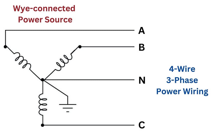
The three “hot” terminals of the source are typically labeled “A”, “B”, and “C”, while the grounded point is referred to as the “Neutral” (N). The voltage measured between any two of the “hot” terminals (A to B, B to C, or A to C) will be \(\sqrt{3}\) times more than the voltage measured between any “hot” terminal and the neutral (A to N, B to N, or C to N). Common voltages for 4-wire wye-connected systems include 208/120 and 480/277.
The existence of dual voltage levels in a center-grounded wye system enables the use of loads with different voltage ratings. For example, in a 208/120 wye system, a three-phase motor with windings rated for 208 volts would draw power from the three “hot” conductors directly, while light bulbs rated for 120 volts would connect between any “hot” conductor and the neutral:

A good practice in such systems is to equally spread the 120 volt loads among the three phases, so that (ideally) the phase loading on the source will be nicely balanced when all loads are operating. If the loading is perfectly balanced, in fact, the neutral conductor will carry no current at the point where it connects to the center of the wye.
Note the use of fuses on all the “hot” load conductors, but no fuses on any “neutral” (grounded) conductor. The reason for this is so that in the event of a fuse blowing, only the hot conductor(s) will be disconnected from the load, leaving the neutral conductor connected and thereby maintaining the lowest possible potential at the load relative to earth ground.
In delta-connected systems, there is no “natural” point to connect to earth ground as there is in wye-connected systems. The most common grounding configuration for a delta-connected source is shown here, sometimes called the “high-leg” connection. Here, one of the source’s phase coils is center-tapped to provide a connection point for earth ground:

This configuration yields three different voltages available to power loads. If the phase voltage of the delta-connected source is 240 volts, the three available voltages are:
- 240 volts (between A-B, B-C, and A-C)
- 120 volts (between B-N and C-N)
- 208 volts (between A-N)
A disadvantage of this configuration is that the lower-voltage loads cannot be balanced among all three phase coils of the source as they can in wye-connected systems. Any single-phase loads (those connected between any one “hot” conductor and the neutral conductor) inevitably place more burden on the B-C phase coil than the other two phase coils. However, this imbalance is often negligible in industrial settings where three-phase loads are predominant and single-phase loads are few (and low-wattage).
Balanced and Unbalanced Three Phase Systems
Balanced three-phase networks are relatively easy to calculate quantities in, as each line and phase variable is symmetrical. For instance, if we happen to know one of the phase voltages in a balanced Wye-connected power system component is 2400 volts, then we may safely conclude the other two phase voltages are 2400 volts as well. The voltage between any two lines in this same system is guaranteed to be \(\sqrt{3}\) larger than any phase voltage: \(2400 \sqrt{3} \approx 4160\) volts.
Calculations become much more complex, however, in unbalanced three-phase networks. One of the assumptions we must discard in an unbalanced network is the simple factor of \(\sqrt{3}\) relating phase and line quantities: while \(V_{line} = V_{phase} \sqrt{3}\) in a balanced Wye-connected system, it is not necessarily true in an unbalanced Wye-connected system. Compare these phasor diagrams of a balanced versus unbalanced 2400/4160 volt Wye systems, the unbalanced system being representative of a three-phase generator with a fault in one of the phase windings causing that phase voltage to be substantially less than it ought to be:

In fact, the existence of faults in three-phase power systems is the primary reason for considering unbalanced systems, since the vast majority of three-phase electrical components are expressly designed to be balanced. If power system engineers and technicians are to analyze faults, they must have some means of quantifying unbalanced system conditions.
Symmetrical Components
A breakthrough in mathematical analysis for unbalanced three-phase electrical circuits came in 1913 from a man named Charles Legeyt Fortescue, who presented his discovery in a paper entitled, “Method of Symmetrical Co-ordinates Applied to the Solution of Polyphase Networks” after doing research on AC induction motors operating under unbalanced conditions. His discovery condenses to the fact that any set of phasors describing conditions of voltage or current in a three-phase network, no matter how unbalanced and asymmetrical they may be, are mathematically equivalent to the sum of three unique phasor sets with different rotations. Thus, it is possible to mathematically decompose an unbalanced phasor triad into multiple sets of balanced phasor triads, each of those balanced sets being relatively easy to analyze on its own because the simple rules of symmetrical networks (e.g. the \(\sqrt{3}\) factor between phase and line quantities) still apply.
Fortescue’s breakthrough is reminiscent of Jean Baptiste Joseph Fourier’s discovery roughly 100 years prior that any periodic waveform, no matter its shape, is mathematically equivalent to a summation of pure sinusoidal waveforms of harmonic frequencies (called a Fourier Series). In both cases, we see there is a mathematical equivalence between one entity that is ugly and asymmetrical, and a set of pure and symmetrical entities that are easier to deal with on mathematical terms.
In Fortescue’s model, which is widely known under the title of symmetrical components, any set of three phasors describing voltage or current in a three-phase system is equivalent to the summation of three different three-phasor sets:
- One set of three phasors rotating in the normal A-B-C direction of the power system, called the positive sequence. By convention, this sequence is designated by the number 1.
- One set of three phasors rotating in the reverse direction (A-C-B), called the negative sequence. By convention, this sequence is designated by the number 2.
- One set of three phasors all pointed in the same direction, having no sequence at all, called the zero sequence. By convention, this sequence is designated by the number 0.

Fortescue’s discovery was that we may synthesize any possible three-phasor set simply by superimposing these positive, negative, and/or zero sequence phasor sets at the appropriate magnitudes and phase shifts. Each positive sequence, negative sequence, and zero sequence set is perfectly balanced, although they must usually differ in magnitude from each other in order for the summation of all three to equal the real-world unbalanced set.
Another way of stating this is to say that the actual voltages and currents in a three-phase power system, no matter how unbalanced they may be from each other, are really equivalent to multiple sets of voltages and currents existing in the circuit simultaneously, each with its own rotational sequence and perfectly balanced magnitude. Our hypothetical three-phase generator with the faulted phase winding, therefore, is really equivalent to three healthy generators with their windings wired together to be series-aiding: one generator spinning in the normal direction, the next generator spinning the wrong direction, and the last generator a single-phase unit with three in-phase windings. The combined sum of these three generators’ outputs would create the exact same patterns of voltages and currents as the one faulted-winding generator:

Let us explore this in more detail by means of a concrete example. Taking the faulted-winding generator whose phasor voltage diagram was shown earlier (phase voltages \(V_A\) and \(V_C\) at 2400 volts each, but phase voltage \(V_B\) at only 240 volts), our task is to see how to decompose this unbalanced set of voltage phasors into three balanced sets of phasors (positive-, negative-, and zero-sequence):

Somehow, we must determine the specific pattern of balanced positive-, negative-, and zero-sequence phasor sets that will be equivalent to the unbalanced phasor set describing our faulted generator. Once we determine these symmetrical components, we will then sum them together to demonstrate how the respective phasors do indeed add up to the original (unbalanced) phasor diagram.
Thankfully, symmetrical component analysis provides us with a set of equations for calculating the “A” phasor of each sequence. Please note that each variable in each of the following equations is a phasor quantity, possessing both a magnitude and a phase angle. Also note that these equations apply just as well to calculations of current as they do to voltage:
\[V_{a1} = {1 \over 3} (V_a + V_b \angle +120^o + V_c \angle +240^o) \hskip 30pt \hbox{Positive-sequence phasor } A\]
\[V_{a2} = {1 \over 3} (V_a + V_b \angle +240^o + V_c \angle +120^o) \hskip 30pt \hbox{Negative-sequence phasor } A\]
\[V_{a0} = {1 \over 3} (V_a + V_b + V_c) \hskip 70pt \hbox{Zero-sequence phasor } A\]
The “+120\(^{o}\)” and “+240\(^{o}\)” references deserve further explanation. What we are saying here is that the calculations involve shifting the angle of the unbalanced system’s phasor by either +120 degrees or +240 degrees when calculating the phasors for the positive and negative sequences. Performing the calculations:
Given phasors in unbalanced system:
\(V_a = 2400 \angle 0^o\)
\(V_b = 240 \angle 240^o\)
\(V_c = 2400 \angle 120^o\)
\[V_{a1} = {1 \over 3} [2400 \angle 0^o + 240 \angle (240^o + 120^o) + 2400 \angle (120^o + 240^o)] = 1680 \angle 0^o\]
\[V_{a2} = {1 \over 3} [2400 \angle 0^o + 240 \angle (240^o + 240^o) + 2400 \angle (120^o + 120^o)] = 720 \angle -60^o\]
\[V_{a0} = {1 \over 3} [2400 \angle 0^o + 240 \angle 240^o + 2400 \angle 120^o] = 720 \angle 60^o\]
Recalling that our faulted generator is mathematically equivalent to three healthy generators with their respective phase windings connected in series, these solutions tell us that the equivalence is one generator spinning the correct direction at 1680 volts per phase, connected to another generator spinning the wrong direction as well as phase-shifted \(-60\) degrees at 720 volts per phase, connected to a single-phase generator phase-shifted +60 degrees at 720 volts per phase. These three healthy generators, each one producing a symmetrical (balanced) set of voltages, will together behave the same as our one 2400 volt phase generator with the faulted “B” winding.
Graphically, the decomposition of the original unbalanced phasor diagram into symmetrical components is as follows:

The graphical proof that these three symmetrical component phasor sets do indeed add up to be equivalent to the original (unbalanced) phasor diagram of the faulted generator is as follows:

In a perfectly balanced three-phase power system, the only sequence in existence is the positive sequence (1). Any and all measurements of voltage and current, therefore, represent the positive sequence of the system. since the magnitudes of the negative- and zero-sequence components are zero. If an imbalance occurs for any reason – from unbalanced single-phase loads on a three-phase power system to actual faults (opens, shorts) – negative-sequence and/or zero-sequence components arise.
While negative-sequence quantities cannot be measured directly by any voltmeter or ammeter, zero-sequence components can. In Y-connected systems, zero-sequence current manifests itself as current through the neutral conductor, while zero-sequence voltage manifests itself as voltage between the center of an ungrounded Wye and ground. Zero-sequence current manifests in Delta-connected systems as current circulating in the phase elements of the source or load.
The following illustration shows a medium-voltage (4160 volt) electric motor circuit equipped with a protective relay to halt the motor in the event its electrical or thermal parameters indicate the potential for damage:

Note the “zero sequence” current transformer (CT) encircling all three lines conducting power to the motor. This large CT magnetically senses the instantaneous sum of currents into and out of the motor, which should be zero under normal operating conditions. If, however, a ground fault develops within the motor, the instantaneous sum of currents will become non-zero, causing the “zero sequence CT” to register some current. If this zero-sequence current becomes large enough, the protective relay will command the contactor feeding power to the motor to trip (open) in order to protect the motor against further damage.
This exact same principle is used in household “GFCI” (Ground Fault Current Interruptor) receptacles and circuit breakers required by the National Electrical Code to be used in “wet” areas of a residence such as bathrooms: a small current transformer senses the net sum of current through the “hot” and “neutral” conductors. If this net current measurement is anything but zero, the interruptor contacts trip, ceasing the flow of power to the load and thereby protecting the person using that load from injury due to ground-fault current passing through their body:

REVIEW:
-
Single phase AC uses one energized and one neutral wire.
-
Three phase uses three equally balanced energized lines.
-
Many three phase systems use neutral to create single phase branch circuits.
-
Ground wires in three phase systems prevent the accidental discharge of energized components through unsafe or unpredictable paths.
-
Symmetry in three phase systems can be achieved by using combinations of positive, negative, and zero-sequence generators.
