 Facebook
 Google
 GitHub
 Linkedin
Resistance, Reactance, and Impedance
Some resistance effects appear when subjected to AC, but not to DC
When subjected to AC voltages, some components introduce a time delay between voltage and current, but they do not dissipate any energy like a resistor. This means that the concept of ‘reactance’ must be considered.
Electrical Resistance
Resistance (\(R\)) is the dissipative opposition to an electric current, analogous to friction encountered by a moving object. In any example of electrical resistance, the electrical energy is converted into some other form of energy that cannot (or does not) return back to the circuit. Resistance may take the form of an actual resistor, in which case the electrical energy is converted into heat. Resistance may also take the form of an electric motor, an electric light, or an electrochemical cell where the electrical energy is converted into mechanical work, photons, or enables an endothermic chemical reaction, respectively.
Electrical Reactance
Reactance (\(X\)) is the opposition to an electric current resulting from energy storage and release between certain components and the rest of the circuit, analogous to inertia of a moving object. Capacitors and inductors are classic examples of “reactive” electrical components, behaving either as electrical loads or as electrical sources depending on whether the applied electrical signal is increasing or decreasing in intensity at that instant in time. This load/source behavior of capacitors and inductors is explained in more detail in the DC electrical theory chapter.
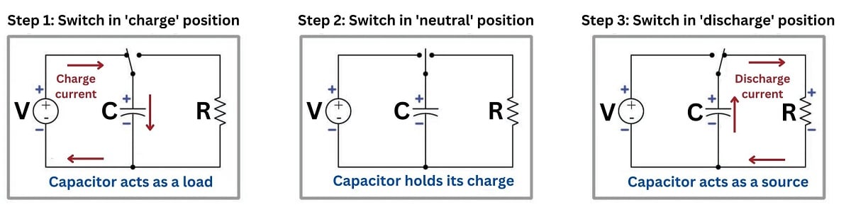
Capacitor acting as a load and a source.
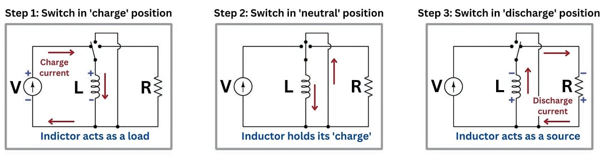
Inductor acting as a load and a source.
When a purely reactive component is subjected to a sinusoidal signal, it will spend exactly half the time behaving as a load (absorbing energy from the circuit) and half the time behaving as a source (returning energy to the circuit). Thus, a purely reactive component neither contributes nor dissipates any net energy in the circuit, but merely exchanges energy back and forth. Even though the fundamental mechanism of reactance (energy storage and release) is different from the fundamental mechanism of resistance (energy conversion and dissipation), reactance and resistance are both expressed in the same unit of measurement: the ohm (\(\Omega\)).
Electrical Impedance
Impedance (\(Z\)) is the combined total opposition to an electric current, usually some combination of electrical resistance (energy dissipation) and electrical reactance (energy storage and release). In order to represent how much of a particular impedance is due to resistance and how much is due to reactance, the value of an impedance may be expressed as a complex number with a “real” part (representing resistance) and an “imaginary” part (representing reactance). This concept will be explored in much more detail later in this chapter during discussions about “phasor” relationships.
Impedance in an AC Circuit
When calculating the total impedance of an AC circuit, the “real” and “imaginary” parts of the circuit intersect at a 90\(^{o}\), leading to a Pythagorean relationship between the two variables:
\[Impedance^2 = Resistance^2 + Reactance^2\]
\[Z^2 = R^2 + X^2\]
\[or\]
\[Z = \sqrt{R^2 + X^2}\]
Since both resistance and reactance are expressed in Ohms (\(\Omega\)), the units of impedance are expressed the same way.
As either reactance (from either capacitive or inductive loading or both) or resistance (from resistive loads) increases, the impedance will grow. In most real-world circuits, the overall load is a combination of both resistance and reactance. If either of these component values is a larger magnitude than the other, the load may be considered to be “resistive” or “reactive”, even though it contains both.
Due to the Pythagorean relationship, the total impedance will always be less than the total sum of the resistance and reactance, assuming both are non-zero values.
Impedance in a DC Circuit
Given a DC voltage supply, capacitors will act as open circuits, raising the impedance to infinity and blocking current entirely. In contrast, an inductor will reduce impedance to zero and will have no additional impact above the resistive load in the circuit. (The math of this statement is proved below.)
For these reasons, we do not include reactance in any DC resistance and current calculation. If we chose to include such components, using the Pythagorean \(Z\) equation above, we would always substitute a \(0\) or \(\infty\) in place of \(X\), producing very predictable results each time. Therefore, the \(X\) component is ignored and we reduce the equation to simply: \(Z=R\).
Capacitive Reactance and Inductive Reactance
The amount of electrical reactance offered by a capacitor or an inductor depends on the frequency of the applied signal. The faster the rate at which an AC signal oscillates back and forth, the more a reactive component tends to react to that signal. The formulae for capacitive reactance (\(X_C\)) and inductive reactance (\(X_L\)) are as follows:
\[X_C = {1 \over {2 \pi f C}}\]
\[X_L = 2 \pi f L\]
In a DC circuit, the frequency of alternation is 0 Hz, proving mathematically from the above formulas that (\(X_C\)) will produce infinite reactance (open circuit), while (\(X_L\)) will produce zero resistance. Therefore, neither component will be factored into the overall resistance in a DC circuit, assuming it is understood that a capacitor produces an open circuit, as noted previously.
When both capacitors and inductors are included in a circuit (as they most likely would, given real-world circumstances), they oppose each other at a 180\(^{o}\) angle, with the inductor being a positive value, and the capacitor being negative when the impedance is being considered. Therefore, the total value of reactance (\(X\)), is the difference between \(X_L\) and \(X_C\).
\[X = X_L - X_C\]
Because of this, the total reactance may be positive or negative. Since the value is squared in the total impedance (\(Z\)) equation, the polarity of the reactance has no bearing on the amount of impedance. However, the polarity of the reactance can indicate the dominant characteristic of the circuit: is it overall more capacitive, or inductive? This answer can lead to certain design choices for both circuit-level and assembly-level designs.
As a related side note, although reactance may be positive or negative, resistance will always be positive. If a negative resistance value is ever encountered on a test instrument during troubleshooting, the circuit is likely still powered and must be immediately removed from power to prevent damage to the meter. More information about this problem can be found in a related technical article.
Power Factor Correction Capacitors in Motor Circuits
Motors are highly inductive loads, requiring higher current when starting and accelerating. Being inductive, they introduce reactance into the circuit, raising the impedance. To counter the effect of induction, banks of ‘Power Factor Correction’ capacitors are often installed either at the electrical service entrance or along problem branch circuits within an industrial facility. The rating and energy storage of these capacitors is matched with the demands of the motors for each application.
Susceptance
Just as conductance (\(G\)) is the reciprocal of resistance (\(1 / R\)), a quantity called susceptance (\(B\)) is the reciprocal of reactance (\(1 / X\)). Susceptance is useful when analyzing parallel-connected reactive components while reactance is useful for analyzing series-connected reactive components, in much the same way that conductance and resistance are useful when analyzing parallel-connected and series-connected resistors, respectively.
Admittance
Impedance (\(Z\)) also has a reciprocal counterpart known as admittance (\(Y\)).
These two final properties, susceptance and admittance, are typically of lower value for a control engineer. These quantities may be useful when determining circuit equivalents for series and parallel combinations when both reactance and resistance are combined in complex circuits.
In most control system settings, each branch is its own series circuit, whether an input such as a sensor or switch, or an output such as a motor control branch. For this reason, it is not very common to find the need to reduce complex equations to simple series equivalents, and the susceptance and admittance find themselves rarely being considered in this industry.
Equivalent Resistance and Equivalent Impedance
Impedance in a series circuit is the orthogonal sum of resistance and reactance:
\[Z = \sqrt{R^2 + X^2}\]
\[Z = \sqrt{R^2 + (X_L - X_C)^2}\]
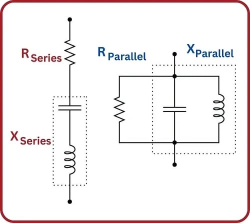
Equivalent series and parallel circuits are circuits that have the exact same total impedance as one another, one with series-connected resistance and reactance, and the other with parallel-connected resistance and reactance. The resistance and reactance values of equivalent series and parallel circuits may be expressed in terms of those circuits’ total impedance:
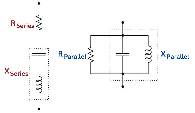
Series Circuit Analysis and Parallel Circuit Analysis
If the total impedance of one circuit (either series or parallel) is known, the component values of the equivalent circuit may be found by algebraically manipulating these equations and solving for the desired \(R\) and \(X\) values:
\[R = \sqrt{Z^2 - (X_L-X_C)^2}\]
\[X = X_L-X_C = \sqrt{Z^2 - R^2}\]
REVIEW:
-
Resistance is the energy conversion from electrical energy into motion, light, or heat. Resistive loads result in ‘true’ or ‘active’ power.
-
Reactance is the energy storage and discharge from capacitors and inductors, so no power is converted to another form. Reactive loads result in ‘reactive’ power.
-
Impedance is the overall opposition to current flow in an AC circuit, resulting in the ‘apparent’ power loss.
-
Impedance is the Pythagorean sum of resistance and reactance.
-
Likewise, apparent power is the Pythagorean sum of active and reactive power.
