Frame 5 PG5361P — Principle of Diesel Starting Means Solenoid Valves 20DA-1 & 20DA-2

Hello everyone,
Our company recently acquired a 1981-vintage PG5361P gas turbine package manufactured by John Brown. We are struggling to understand the true principle of the 20DA-1 (Intermediate) and 20DA-2 (Maximum) solenoid valves in the diesel starting means control circuit, and would greatly appreciate your insights.
The diesel engine starts via 88DS and stabilizes at ~600 rpm idle under its own mechanical governor, with both 20DA-1 and 20DA-2 de-energized. This appears to be the natural idle speed of the diesel.
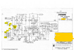
Our P&ID shows that 20DA-1 and 20DA-2 share a common control oil circuit feeding the same fuel rack actuator (governor actuator). The control logic indicates they are interlocked — only one can be energized at a time.
Our field tests show the following:
  • When 20DA-2 (Maximum) is energized, the actuator drives the fuel rack to full fuel, the diesel accelerates rapidly, and the gas turbine reaches ~1300 rpm. This behavior is clear and repeatable.
  • When 20DA-1 (Intermediate) is energized, the actuator appears to see equal pressure on both sides based on our reading of the schematic. The fuel rack does not move, and the diesel speed remains at ~600 rpm idle — exactly the same as when 20DA-1 is de-energized.
We can hear the 20DA-1 coil energizing and de-energizing (audible click), so the solenoid armature is moving. However, we cannot confirm if the internal spool is actually shifting, or if the valve is simply ported in a way that balances actuator pressure without producing rack movement.
If the diesel naturally idles at 600 rpm with neither solenoid energized, and energizing 20DA-1 does not increase the speed above 600 rpm, then what is the actual purpose of 20DA-1?
We have two competing hypotheses:
  1. "Speed-Hold" Hypothesis: 20DA-1 is not meant to raise speed from idle, but rather to mechanically lock the fuel rack at the intermediate position when 20DA-2 is de-energized — preventing the rack from falling all the way back to idle (or zero) during the transition from maximum speed down to cranking/locking speed. In other words, 20DA-1 only "works" when the rack is already at the intermediate position, not when it is at idle.
  2. "Speed-Raise" Hypothesis: 20DA-1 should raise the diesel from 600 rpm idle to a higher intermediate speed (e.g., 900–1000 rpm for cranking/locking). If so, our unit has a fault — most likely a stuck internal spool, a misadjusted or detached mechanical stop, or a blocked oil passage inside the 20DA-1 valve.
Our Questions:
  1. For a 1981 John Brown Frame 5 package, does 20DA-1 actually command a diesel speed higher than the natural 600 rpm idle, or is its role purely to hold the rack at intermediate position during deceleration from 20DA-2?
  2. If 20DA-1 is indeed supposed to raise speed from idle, what is the typical diesel speed setpoint for the intermediate position on these vintage units?
  3. Given that 20DA-2 functions perfectly but 20DA-1 produces zero speed change from the 600 rpm baseline, what is the most probable root cause — spool sticking, mechanical stop issue, or misunderstanding of the intended logic?
Attached is the diesel starting means schematic that matches our unit.
Looking forward for your reply!
Thanks!
 

Attachments

QUOTE="plciscool, post: 227027, member: 48580"]
Do you have the valve schematic?
[/QUOTE]
Hi plciscool,
Thank you for your response.
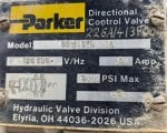
I do not have the manufacturer's official valve schematic. However, I have attached a clear photo of the actual valve nameplate here for your reference. Both 20DA-1 and 20DA-2 are the exact same model.20DA nameplate.jpg
 
We had a 1980 vintage GE Frame 6 with same set up. Your first hypothesis is correct I believe.
On our system:
After the diesel warm up time the acceleration solenoid (20DA-2) is energized to drive the actuator to the full power position.
Once diesel reaches 83% of its full speed (about 1900 rpm), the acceleration solenoid (20DA-2) is de-energized, driving the cylinder back towards idle speed.
As the diesel speed drops back to 75% of its full speed (about 1725 rpm), the holding solenoid 20 DA-1 is energized to apply the pressure to both ends of the cylinder. This holds the throttle at an intermediate speed.
At this diesel speed the turbine should reach its minimum firing speed of 16%.
After the GT is lit off and goes through its warm up period, the solenoids switch to drive the diesel to full speed to assist the gas turbine with its acceleration. Once the GT outruns the diesel and disengages the clutch, the solenoids are de-energized to drive the diesel back down to idle for its cool down period.
As I recall we had an issue of the speed of the diesel speed decaying during the GT purge cycle. I guess moving air through the turbine heated things up a little and changed the load on the diesel (??). The design only held the throttle steady at some open position. We had to add a little "nudge " logic to swap the solenoids momentarily and re-accelerate the diesel once the speed decayed a significant amount.
 

Attachments

Hi MWO,
Thank you very much for your detailed explanation, it is extremely helpful.
I have a follow-up question regarding the 20DA-1 energizing logic at the 75% diesel speed setpoint.
On our Frame 5 unit, the diesel engine only has a local tachometer for speed indication; there is no speed probe sending the diesel RPM signal back to the turbine control system.
Could you please clarify how the 20DA-1 is triggered at the specific diesel speed on your Frame 6 unit? Does your diesel have a remote speed probe wired to the Mark control system? Or is 20DA-1 energized based on the gas turbine speed dropping to a certain percentage after 20DA-2 is de-energized, rather than directly sensing the diesel RPM?
Also, if possible, would you mind sharing the diesel starting means piping diagram from your Frame 6 unit? It would be a valuable reference for us to compare with our Frame 5 system.
Thanks again for your time and generous help!
 
Hi MWO,
No problem at all regarding the drawings, and thank you again for sharing your valuable field experience from the Frame 6 unit. It has been extremely helpful in understanding the logic on our Frame 5.
Wish you a happy retirement!
 
Device summary:
20DA1 - Energize to lock speed control in an existing intermediate position Normal =P to plugged port A; B to T Open
20DA2- Energize only for max power Normal =P to plugged port A; B to T Open
20DV-1 - Stop solenoid

Operation:
After the starting clutch is engaged, 88DS-1 is energized to start the engine. The engine idles through the warm-up cycle, and then 20DA-2 is energized to accelerate the engine to maximum speed for unit breakaway (requires assistance of the hydraulic ratchet). Following breakaway, 20DA-2 is de-energized to decelerate the engine to approximately 1900 rpm, at which point 20DA-1 is energized to hold constant engine speed until the gas turbine is sequenced through the end of warm-up. Then 20DA-1 is de-energized and 20DA-2 energized to accelerate the engine back to maximum speed (and power) for acceleration of the unit to self-sustaining speed. At a unit speed of about 3100 to 3200 rpm, the clutch automatically disengages, and 20DA-2 is de-energized. The engine returns to idle speed, idles through a cool-down period, and stops when 20DV-1 is energized for several seconds.1785723328833.png
 
Hi vscontrol,
Thank you very much for sharing the Device Summary and the detailed Operation sequence — this is exactly what I was looking for, and it perfectly clears up my confusion.
Now I fully understand the logic:
(1)20DA-1 is indeed a "speed-hold" solenoid: it does not raise the diesel from idle, but rather locks the fuel rack at the intermediate position once the diesel has decelerated from max speed down to ~1900 rpm, maintaining constant speed during the GT warm-up and purge phase.
(2)20DA-2 is the "acceleration" solenoid: it drives the rack to full power for breakaway and again for accelerating the GT to self-sustaining speed.
(3)The sequence of 20DA-2 energize → 20DA-2 de-energize → 20DA-1 energize → 20DA-1 de-energize → 20DA-2 energize → 20DA-2 de-energize now makes complete sense.
This also explains why on our Frame 5 unit, energizing 20DA-1 at idle (~600 rpm) produces no speed change — the rack is already at the idle position, and 20DA-1 simply holds it there.
Thank you again for your time and for providing such precise documentation. It is extremely valuable for us in commissioning this 1981 John Brown package.
Best regards
 
Top