Facebook
 Google
 GitHub
 Linkedin
Parallel Load Devices: Multiple AC Motors on One Control Circuit
Requiring multiple AC motors to start simultaneously is a common need for conveyors within manufacturing plants, but can we really reduce costs and panel space by eliminating redundant components?
A common conveyor layout in a manufacturing plant is a modular belt system driven by many motors. Each motor drives a section of conveyor, and longer conveyors are constructed of multiple sections, straight and curved as required. Many of these motors need to start and stop at the same time. You could construct each motor with independent logic and contactor control, or you could wire all the coils of the contactors together so that all of the motors start at the same time… But is it possible to use only one contactor to control all the required motors in the circuit?
In this article, I will cover parallel motor control wiring and how you might be able to reduce the number of components, investigating the details of that required component list.
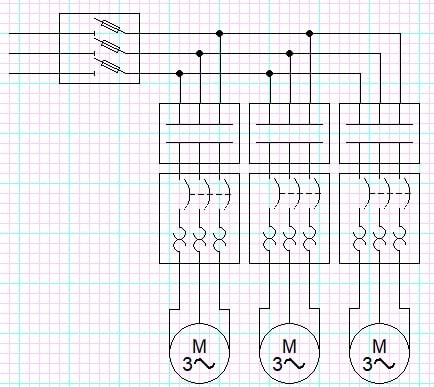
Figure 1. A typical multi-motor layout with isolated contactors. Image used courtesy of the author
The Circuit Layout
To run multiple motors off the same control circuit, you first need to make sure that the single controlling contactor must be rated for the sum of all the motors’ full-load currents, accounting for startup (inrush) amperage.
You will also need a distribution block to connect all the motors to the same circuit, as most contactors will only have three output terminals. So if you are using three-phase motors, you will need three distribution blocks that can handle all of the current required in the circuit.
Finally, you must ensure that each motor has its own overload protection. According to NEC standard 430.53 Group Motor Installation, each motor must have an overload sized for the specific downstream motor.
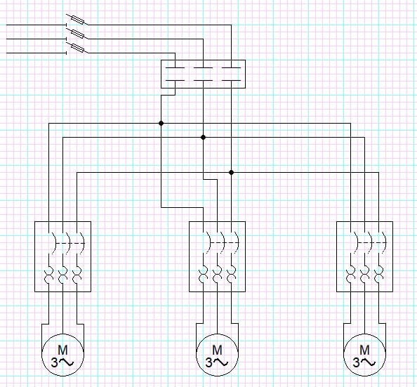
Figure 2. Single contactor driving 3x three-phase motors. Image used courtesy of the author
Sidebar note: Single-phase motors are a bit different, since 120 V, 1-ph motors have one live wire and one neutral, so a 3-pole contactor could supply up to three motors. On the other hand, a 240 V, 1-ph motor has two live wires, so a distribution block would be necessary for paralleling any multiple of these motors.
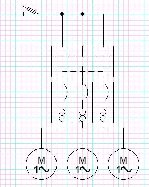
Figure 3. 3x single-phase, low-voltage motors driven by one control contactor. Image used courtesy of the author
Circuit Protection
In a typical control circuit, you would have a short-circuit protection device (fuse or circuit breaker) and a branch circuit protection device (overload) for each motor. Since we are trying to reduce the number of devices, we can use a single fuse to protect all of the motors within the circuit and only an overload device for each motor.
To size the fuse, use the largest motor's maximum allowed protective rating plus the sum of full-load amperages of the remaining motors in the circuit. NEC 430.53 also states that the short-circuit protection device must be sized to support starting loads of all connected motors; the system must not experience nuisance faults.
Costs Savings
While it is possible to control multiple motors with a single contactor, it may not be worth the hassle. Since all individual motors must have an overload protection device, overloads are often sold or coupled with contactors already attached. The other problem is that the contactor must be sized to support all of the load downstream, so you will need to oversize your contactor, and these larger contactors can be difficult to find.
Larger contactors can also be far more expensive. A standard low-current, around 9 A, contactor ranges in price from $20 to $40 depending on the manufacturer and the number of auxiliary contacts. Contactors with current ratings of >100 amps can cost well over $300.
So, depending on the number of motors within the circuit and the size of the motors, it might actually be more expensive to have a single contactor than to provide individual contactors.
Single Control
If your ultimate goal is to control multiple motors with one signal source signal, there may be an alternative that retains individual contactors for each motor. This method is to design your circuit with individual contactors and wire all the contactor coils in parallel. This would energize all the contactors at the same time.
You will need to make sure your controller can handle the inrush current of the coils connected, so be sure to check out the datasheet ratings for this inrush current (also called startup or pull-in current). Another popular method is to have the PLC output drive a relay that sends the control voltage right from the power supply. Nearly any mechanical relay is more than capable of handling the current required for a few contactor coils.
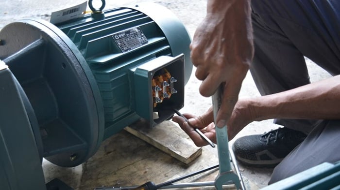
Figure 4. A typical motor installation. Image used courtesy of Unsplash
The Result
Admittedly, this isn’t a super common practice, but there might be some scenarios where a single contactor layout might be applicable, such as limited panel space, limited number of PLC outputs, or when you are working with small motors in simple applications.
Keep in mind that if your system is using three-phase motors, the combined required current rating of the contactor required to control this circuit might be more costly than having multiple contactors.
The design, budget, and space requirements of the application will dictate how you can control multiple motors with one control signal. While it may be possible, it is not always economical.
Related Content