GE Mark VI not in control state

Dear All,
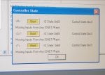
Recently our battery system has disturbance and causing our tmr mark vi rebooted. Unfortunately after reboot, the R and T status become fail and S in boot status with alarm missing any IO net/rack. We tried to do hard boot but still fail and led not synchrone.
Based on the past thread we did this step:
1. Download product code then hard boot (vpro & r-s-t)
2. Download app code check only put to memory then hard boot
3. Download config and firmware then hard boot
4. Download app code to memory
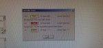
But that didn't work. We even tried to do compact flash ucvg but the result still not in control state. Ping ucvg IP address is good. The last result we get is all processor in boot state (yellow) and alarm missing any ionet/rack, also control state 0xC3. App code is equal (green) . All BNC cable is still good. But 1 vpro card in R is fail. But I think one VPRO fail is not causing this and we have experience 1 vpro before and all r-s-t still good. We tried to put new vcmi and download config and ther result still same.
Anyone have to solve this experience before? Can you please share the step for resolving this issue.. the gas turbine can not run now.. and we ran out of idea to put mark vi back to control state.

Thanks
 
briq99,

My (painful) similar experience has led me to these practices, but patience is a BIG key under these circumstances:

1) Make sure ALL the IONET cables are good, and that there is no corrosion or discoloration on any of the BNC connectors on the cables, including BNC tee connectors. Good, clean connections are essential for communications, which are essential for establishing "control mode."

2) Power down ALL the processors and processor racks from the <PD> Power Distribution module: <X>, <Y>, <Z>, <R>, <S> & <T>. (It's not necessary to remove power to the contact input terminal boards or the solenoid output terminal boards.) All the processors/processor racks need to be off. (I leave the ON-OFF switches on the rack-mounted power supplies in the ON position, and just use the switches in the <PD> module to remove and apply power to the processors and processor racks.)

3) Apply power to <X> by closing the <X> switch in the <PD>, wait about 10 seconds then apply power to <Y> by closing the <X> switch in the <PD>, wait about 10 seconds then apply power to <T> by closing the <X> switch in the <PD>.

4) Apply power to <R> by closing the switch for <R> in the <PD> module. (Some people also use the power switch on the rack-mounted power supplies to apply and remove power; if you opened the power switch on the rack-mounted power supply of <R>, close it to complete the application of power to the <R> processor rack.) Watch the LEDs of the UCVx and also of all the other cards in the <R> processor rack, and the LEDs on the <X> processor. Often times shortly after power is applied to the UCVx card, there is a short and muffled (low volume) beep from the UCVx card. Sometimes it's barely audible, and some versions of the UCVx card and Mark VI firmware seem to not have the beep; but it's a good idea to listen for it to know if your panel and firmware revisions emit the beep in the future when troubleshooting. But be patient and watch all the LEDS on the UCVx card, all the I/O cards in the <R> processor rack as well as the VPRO. Eventually, all of the green LEDs on the I/O cards in the <R> processor rack will start flashing at different rates, and--if things are "good" eventually they should all start flashing in unison (flashing on and off at the same time and the same rate). Sometimes it can take four or five painfully long minutes for all the greed LEDs on the I/O cards to be flashing in unison. If after 5 or 6 minutes they are flashing, but are not "synching up" (flashing in unison), then something else might be the problem (usually the VCMI or IONET cables/connectors), but when this happens (green LEDs not flashing in unison, on an off at the same time and same rate), I find that there is a RED LED on the VCMI card that is either lit or flashing and that indicates something is amiss with the VCMI or the IONET cables/connectors. I don't recall exactly, but I also think there are flashing green LEDs on the UCVx card and the VPRO card (one greed LED on each card) which, eventually, should also be flashing in unison with all the other greed LEDs on the I/O cards. Once all the greed LEDs on all the cards in <R> and on <X> are flashing in unison (on and off at the same time and at the same rate), WAIT for another minute or two. (What's another minute or two at this point, right? The unit's down; just be patient.)

At this point you should be able to connect to the panel using Toolbox to see data and diagnostic information for <R> and possibly for <X>, <Y> and <Z>.

And for the purposes of this procedure, I'm going to presume all the green I/O card leds of <R> are flashing in unison. If one or two I/O cards have yellow LEDs that are lit, and possibly flashing, instead of the greed LED, that's not usually going to prevent the processors from all reaching "control state" but it is an indication of Diagnostic Alarms/problems with the cards with the yellow LEDs. You should be able to use Toolbox to look at each I/O card with yellow LEDs to determine what might be the problem.

5) Apply power to <S>, and be patient--also trying to listen for the beep sound. (If you heard a beep from <R> shortly after power was applied to it, then you should also hear a beep from <S>; if you didn't hear a beep when power was applied to <R>, you may or may not hear a beep when power is applied to <S>--but try to listen for it and make a note if you do or don't hear it. Wait to see if all the green LEDs on the I/O cards in <S> start flashing, and then slowly start blinking in unison (on and off at the same time and at the same rate), including the <Y> VPRO card. Again, this could take several minutes to happen; if all of the green LEDs are flashing on and off but not at the same time, still wait for a couple more minutes. Also, look for the red LED on the VCMI of <S> and <R>; they should NOT be lit, but if either or both are, that signifies a problem with either the IONET cables or connectors or the VCMI card(s). As with <R>, the green LEDs should all (or most of them anyway) should all be flashing and slowly "synch up" and start flashing in unison (on and off at the same time and at the same rate).

EVENTUALLY, if all is very good, then the LEDs of <R> and <S> will all begin flashing in unison for both processor racks!

6) Apply power to <T>, and listen for the beep and make note of whether you hear it or not. (As with the other processors, if you heard the beep from them shortly after power was applied, you should also hear it from <T>. If you didn't hear any beeps from the other processors when power was applied, then you probably won't hear one from <T>--but listen, and note whether you heard it or not.) Again, after a few minutes, the green LEDs of the I/O cards in <T> should start flashing (at least most of them anyway), and eventually they should "synch up" and all start flashing in unison. AND, if all is VERY good then the greed LEDs of all three processor racks (<R>, <S> and <T>) and the three VPROs (<X>, <Y> and <Z>) should all be flashing in unison (or the majority of them should all be flashing in unison--if there were pre-exisiting Diagnostic Alarms on a few of the I/O cards, then the yellow LEDs of those cards will be lit (and may be flashing) and those cards should be troubleshot to try to restore them to Normal operation.


At this point, hopefully, the panel is in the "control state" and all is good (well, mostly good--because there still might be a couple of I/O cards with yellow LEDs). If not, I strongly suspect there are problems with the IONET cables, the BNC connectors of the I/O cabling, and/or the VCMI cards--and possibly one or more of the VPRO cards. It's also possible that there are problems with the rack-mounted power supplies--but there should be yellow or red LEDs on them to indicate a problem, and it should still be possible to use Toolbox to check the individual rack power supplies (if I remember correctly; I just can't remember precisely how to do that).

The point of this procedure is that I have learned (quite painfully) that with the Mark VI it seems to want the processor power-up procedure to start with <R>, then <S> and then <T>. I haven't found that the sequence of powering-up the VPROs makes any difference--but they DO have to be powered up for the IONETs to get working--so that's why I power them up first.

I have also worked on a couple of panels which had to be completely powered down like above, then the VPROs powered-up, and then power applied first to <R>, then after waiting for about 15 seconds then to <S>, then after waiting another 15 seconds to <T>. But, it still has to be in the sequence of <R>, <S> and <T> when powering-up from all three processors being off (powered-down).

When I first started working on Mark VI, it didn't seem to make any difference which processor was powered-up first during a panel power-up. From my Mark V experience, I always found that starting from <T>, then progressing to <S> then <R> was most effective, and I started that practice with Mark VI turbine control panels, also. But, recently, I have come to learn (painfully) that something in the firmware or whatever seems to require the power-up from a "cold state" requires the sequence to be <R>, then <S> then <T>. Since I started doing that, I have had very few, if any, actually, problems.

Anyway, I don't have access to a Mark VI at this writing. I could probably have provided more detail if I had had access to a Mark VI (my memory is good, but it's not great!). I hope this helps!

If you write back for further help, we need to know what those green LEDs on the I/O cards are doing in each processor rack. We need to know if the red LED on any of the VDMI cards is lit. We need to know if the greed LEDs on the VPROs are also flashing in synch with those of their respective processor rack. You should be able to make screen captures of the window that's telling you the states of the processors (or take and post CLEAR photos) of the window to the thread.

And, if you succeed in achieving "control state" by following the above procedures, please write back to let us know!
 
CSA,
Thanks for your response.
Before I power down from <x><y><z> then <r><s><t>, and vice versa for power up.I'm aware that it is better that the reboot sequence is from <r> first because we ever face almost same problem couple years ago after updating EGD (caused by we did power up from T first) and after we power up from R first everything is going back to normal.. it's different with mark v which we can easily power up from <T> or <S>..
The condition before I left the site is all Green LED on IO <r> <s> <t> and already synch.. i forget to monitor VCMI LED. But I remember there is orange LED flashing at VCMI..
And what if there is problem with VCMI? Is it not enough with download config and firmware? Are there any other ways to config VCMI?
I will try your reboot procedure after reaching the site and inform the result.
Thanks
 

Attachments

briq99,

Hmmm... I always just follow the procedure for replacing the VCMI in GEH-6421 and I haven't had any problems. The only way I know of to configure the VCMI is by downloading to it using Toolbox.

This is another big reason when something like this happens to a working panel (meaning it was working before it was powered-down) NOT to start downloading this, that and the other thing, doing builds and such. (There are OTHER reasons for not doing builds, too, on Mark VI!!!)

So, it sounds like all the I/O cards are synched up on each processor, BUT the VCMIs can't share information for some reason. If there's an orange LED lit on the VCMI, then I think you should try using Toolbox to connect to the panel and go to the VCMI card (it's usually in the individual, SIMPLEX, rack section of Hardware) to see what Diagnostic Alarms are there. Once you have the Diagnostic Alarm Drop Number, you can then go to the VCMI card section of GEH-6421 and look up the alarm and what to do using the Drop Number. (Of course, sometimes the descriptions are cryptic, but it's all there is. You could try telling us what the Drop Number and message you are getting is and maybe someone can help with an idea or suggestion.)

There is something about downloading "topology" to the VCMIs. I think you can see that when you connect to the panel (successfully) with Toolbox, right-click on the VCMI and click on Download and look for something called "Topology." It's been a long time, but I seem to recall this being a problem once in a while. There might not be a specific download option called Topology, but I think just downloading to the VCMI "from" the VCMI in Toolbox does include the topology.

Again, when a panel was working (like it was before the battery problem forced the shutdown of the panel), it's best NOT to just start downloading until you've tried just about everything else.

Please write back to let us know what you find and how you fare. Also, try the "trick" of powering down all three <R>, <S> and <T> and then powering up <R>, waiting about 15 seconds or so and then powering up <S>, and waiting another 15 seconds or so and then powering up <T>.

Hope this helps!
 
CSA,
When we replace failed VPRO, all controller state back to control (green).
This is very weird, in our previous experience 1 vpro fail not make control status goes to boot.
Anyway, thanks for your help
 
briq99,

Thank you VERY MUCH for the feedback?

Which VPRO did you replace?

And, I believe you said you saw an orange LED on at least one of the VCMIs; can you recall which one it was (and if it was red or orange)?

In any case, also, know that the VPRO is on the IONET, so that can cause unexpected issues when the IONET function (hardware/software) fails in a particular way (and, no, I don't know exactly what that way is; I just know I have had a similar experience). The IONET is very important to establishing the designated processor and for synchronizing--and maintaining synchronization--of all of the processors (UCVx's and VPRO's, and VCMI's).

Again, thanks for the feedback! "Feedback is the most important contribution!"(c) It's the thing that really makes Control.com stand out from similar forums.
 
Hello guys, hope everyone is staying.
I have a Mark VI TMR panel I'm trying to commission, I have cloned a working HDD from a running MKVI to be used. I have established comms with the controller, downloaded and uploaded to the Mark Vi But some errors and major difference (as expected) are standing. Any ideas on how to resolve it? If you need more information to assist I am ready to provide it.
Thanks guys. Merry Christmas
 

Attachments

CSA,
When we replace failed VPRO, all controller state back to control (green).
This is very weird, in our previous experience 1 vpro fail not make control status goes to boot.
Anyway, thanks for your help

BRIQ99 & CHeedee (this applies to your situation)
This issue happens only when rebooting the system. The Mark VI (& VIe) requires that ALL IO modules be 100% communicating upon startup. So if you lose the VPRO when the Mark VI is already online & Controlling, then it will continue to run. However if then all 3 controllers are rebooted, you will see issues.
 
We have Mark VI controllers for the GE SC-5 Steam turbine. The same thing happened to us recently.

We observed two burnt MOVs in PDM module and decided to power down all the controllers to replace the PDM module. After the replacement, we started <R>, <S>, and <T> controllers and VPRO cards <X>, <Y>, and <Z> in that order with some delay of 2-3 minutes allowing them to boot.

Although all three controllers and VPRO cards are started without any fault indication, when we try to go online through the toolbox software, it shows "Fail" state instead of "Control" state. Diagnostic codes 92 and 75 appeared in UCVG. Then we powered down all controllers and started again <X>, <Y>, <Z>, <R>, <S>, and <T> order with some delay of around 4-5 minutes allowing them to boot. That attempt also not succeeded.

Then, again all the controllers powered down and started in the order of <R>, <S>, <T>, <X>, <Y>, and <Z> without any delay between switching on the controllers as per the instruction of GE control TA. Then the problem was resolved and "Control" state appeared in the toolbox..!

A similar incident happened in Mark VI controller of GE Frame 9E Gas turbine last year. Mark VI controller panel was powered down by accidentally switching off the source MCB. That time, the source MCB was switched ON allowing powering up all <R>, <S>, <T>, <X>, <Y>, and <Z> at once and controllers were started without any error.

Therefore, it seems, switching ON all the controllers at the same time also can resolve this issue. Nut the result can be varied depending on the reason behind the issue.
 

Attachments

Top