Facebook
 Google
 GitHub
 Linkedin
I am totally dumb when it comes to PLC/ladder logic so please for indulgence.
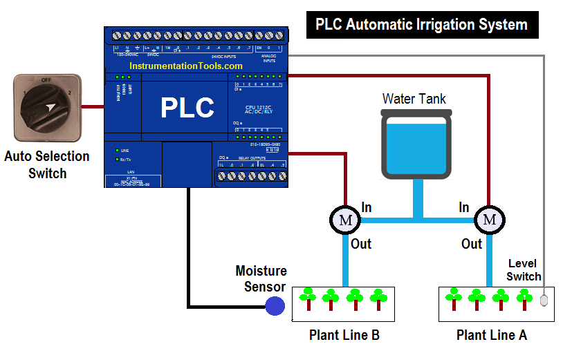
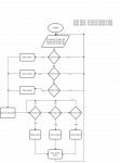
We have subject about PLCs an we have to make project (CoDeSys), mine is about: Automatic Irrigation System. I have few problems with it, but first I'll present how it should work (algorithm block in attachment):
I declared inputs and outputs
inputs:
M1min: BOOL; (*minimum moisture on area1, sensor1*)
M1max: BOOL; (*maximum moisture on area1, sensor1*)
M2min: BOOL; (*minimum moisture on area2, sensor2*)
M2max: BOOL; (*maximum moisture on area2, sensor2*)
M3min: BOOL; (*minimum moisture on area3, sensor3*)
M3max: BOOL; (*maximum moisture on area3, sensor3*)
outputs:
valve1: BOOL; (*valve1*)
valve2: BOOL; (*valve2*)
valve3: BOOL; (*valve3*)
pump: BOOL; (*pump*)
How it works:
1) I declare minimum moisture Mmin=30% and maximum moisture Mmax=90%.
2) Simultanously program checks if moisture on any of three areas is below 30%. If no program backs to the beginning. If yes program opens valves whose correspond with areas and then pump turns on.
3) Water flows and programs checks if moisture on any of three areas is above 90%. If no program backs to the beginning. If yes program closes valves whose correspond with areas and then pump turns off.
4) Program backs to the beginning.
Here are my problems and doubts:
1) The moisture values are BOOL (1/0). How to make them to work like INT (0,1,...,100). I have been thinking maybe use slider for each area? When I move slider below 30% pump will turn on (Mmin controls turn red) and when I move it below 90% the pump will turn off (Mmax controls turn red). But I have totally no idea how to make it. Or maybe is better much simple solution?
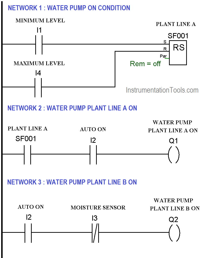
2) I wrote prototypical program in ladder (please don't laugh) which I think to work but it is not exactly what I wanted to achieve.
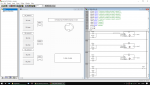
I attach: block algorithm, CoDeSys file and CoDeSys screenshot.
I really hope if someone will help and clearly explain how to solve it. Thank you so much in advance.
We have subject about PLCs an we have to make project (CoDeSys), mine is about: Automatic Irrigation System. I have few problems with it, but first I'll present how it should work (algorithm block in attachment):
I declared inputs and outputs
inputs:
M1min: BOOL; (*minimum moisture on area1, sensor1*)
M1max: BOOL; (*maximum moisture on area1, sensor1*)
M2min: BOOL; (*minimum moisture on area2, sensor2*)
M2max: BOOL; (*maximum moisture on area2, sensor2*)
M3min: BOOL; (*minimum moisture on area3, sensor3*)
M3max: BOOL; (*maximum moisture on area3, sensor3*)
outputs:
valve1: BOOL; (*valve1*)
valve2: BOOL; (*valve2*)
valve3: BOOL; (*valve3*)
pump: BOOL; (*pump*)
How it works:
1) I declare minimum moisture Mmin=30% and maximum moisture Mmax=90%.
2) Simultanously program checks if moisture on any of three areas is below 30%. If no program backs to the beginning. If yes program opens valves whose correspond with areas and then pump turns on.
3) Water flows and programs checks if moisture on any of three areas is above 90%. If no program backs to the beginning. If yes program closes valves whose correspond with areas and then pump turns off.
4) Program backs to the beginning.
Here are my problems and doubts:
1) The moisture values are BOOL (1/0). How to make them to work like INT (0,1,...,100). I have been thinking maybe use slider for each area? When I move slider below 30% pump will turn on (Mmin controls turn red) and when I move it below 90% the pump will turn off (Mmax controls turn red). But I have totally no idea how to make it. Or maybe is better much simple solution?
2) I wrote prototypical program in ladder (please don't laugh) which I think to work but it is not exactly what I wanted to achieve.
I attach: block algorithm, CoDeSys file and CoDeSys screenshot.
I really hope if someone will help and clearly explain how to solve it. Thank you so much in advance.
Attachments
-
 49.6 KB Views: 42
 -
 272.1 KB Views: 56
 -
6.3 KB Views: 23