Endress_Hauser DP Pressure level transmitter error in LRV & URV

Hello Team,
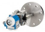
We are using Endress+Hauser DP Pressure level transmitter in our all tanks. In one of the level transmitter giving erratic reading on SCADA which need to replace with new one. Before replacement i have communicated with the transmitter and saved all the settings via HART communicator.
In settings i found the LRV & URV are set -850 & 2770 mmH2O.
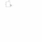
Pls see the attached file for Fuel tank. Tank height is 4000mm, Transmitter is installed at height of tank 420mm from bottom of tank. There is 3 mtr HP capillary connected to flange which is connected at tank fluid sensing point which is 420mm above from bottom. LP is connected to atmospheric pressure with small pipe. It is a closed tank, but venting pipe is open from top of the tank.
Pls help me to calculate the LRV & URV in mmH2O. SG is 0.9.
I could not understand whether this -850 & 2770 mmH2O settings are correct or incorrect.
Kindly share your valuable comments.
 

Attachments

The specific gravity of the capillary fill fluid is missing.

The level can only be read between the lower flange access point and the upper level. Hydrostatic measurements cannot read levels below the lower access point because the hydrostatic force of the liquid below the lower access point does not impinge on the sensing diaphragm

So the measurable level is between the lower flange access point (420mm?) and the upper level 4,000mm

So the measurable range is 4,000mm - 420mm = 3,580mm physical level.

With a liquid medium specific gravity of 0.9, a 3,580 mm physical level would generate a hydrostatic pressure of 3,222mm H2O (3,580*0.9).

When the transmitter is mounted at exactly the same elevation as the lower flange access point, then there is no offset in the LRV reading;
the LRV = 0.0mm H2O
the URV = 3,222mm H2O
total span = 3,222mm H2O

When the transmitter is mounted above the lower flange access point, the fill fluid pulls down on the measuring cell and creates a negative reading.
If the transmitter were physically 100mm below the lower flange access point;
the LRV = -90.0 mmH2O (compensated for SG = 0.9; 100mm*0.9)
the URV = 3,132 mmH2O
total span = 3,222 mm H2O

When the transmitter is mounted below the lower flange, the fill fluid adds its hydrostatic pressure to the pressure on the capillary's sensing diaphragm.
If the transmitter were physically 100mm above the lower flange access point;
the LRV= 90mm H2O
the URV = 3,312 mmH2O (90mm at zero plus the full 3,132 mm from flange access point to upper level)
total span = 3,222 mm H2O

The receiver divides the received measurement value by 0.9 to get the physical level value (or multiplies by 1.111)

I'm guessing that the transmitter is mounted 945mm above the lower flange access point so the LRV is a negative value being mounted above the lower flange access point.
LRV = 945mm (physical *0.9 = 850 mmH2O * -1 for mounting above the access point = -850mm H2O for the LRV

With a URV of 2770mm H2O, that would have a total span of 2770 plus 850 = 3,620mm H2O, which when corrected for the SG would be 4,022mm upper physical level.

The specific gravity of the fill fluid is not accounted for.

Close enough for government work.
 
Dear Mr. David,
Thanks a lot for your valuable comments and it is now very much understood the logic behind to calculate the -850 & 2770 mmH2O LRV & URV, if DP Level transmitter is equipped with long HP capillary tube.

Yes, you were corrected that the level transmitter is installed at height of 945 mm from center of the flange, where HP capillary flange is connected to tank to sense the hydrostatic pressure.

Now in the new DP Level transmitter the HP doesn't have any leg in the form of capillary tube, and it is connected directly on the flange of tank to sense the hydrostatic pressure. Pls see the attached image of new level transmitter.

For this new transmitter the calculation should be as following below which you have already mentioned in your answer,

When the transmitter is mounted at exactly the same elevation as the lower flange access point, then there is no offset in the LRV reading;
the LRV = 0.0mm H2O
the URV = 3,222mm H2O
total span = 3,222mm H2O

Kindly pls confirm that these above settings are correct as per new DP level transmitter.

Thanking you in advance.
 

Attachments

Top