Energy Metering Communicating Gibberish & Incorrect Info over Modbus RTU

Hello, this is my first thread, and Im seeking advice from the experts as I'm at my wits end.
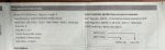
I've connected to a hager energy meter (I've already contacted their customer support) to my windows laptop, where Im running SSCOM to communicate with the metering. When I try and communicate, I either receive incorrectly formatted responses, where the slave address and function code aren't the same ones I sent it to, the response is too short, nothing matches what it's supposed to be, etc, or I receive correctly formatted responses that can't possibly be right, like having a voltage of 0, when I expect something closer to 100V. And I'll receive a mix of these responses for identical communication sent out.

I've triple checked the settings, that everything is on the correct port, baud rate, serial port, everything I can think of. I've checked the information Im sending, and I think it's correct but perhaps one of you could point out what Im missing.

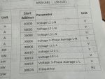
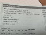
When I treat the start addresses as literal decimals, minus 30000, I get wacky responses. If I convert the 30xxx from hex to decimal, I get an exception response error (top of ss). In both situations, the energy meter shows that RS 485 communication is taking place.
 

Attachments

I'm not 100% sure, but judging from the sparse information you posted I think the data is in float format, but comes in in separate word (16 bits signed/unsigned) registers.
From there you need to convert the separate registers into a real (floating point) number. I see something about float in right top of 1 of your pictures.
Standard modbus has no support for floating point numbers, but there are examples of implementations you can use.

Here's some page on this: https://store.chipkin.com/articles/...tance of Byte Order,order of the data payload.

Sometimes these units also have 16 bit unsigned (or signed) word registers next to the floating point registers that you can use instead of the float.
Then for example on 1 register the voltage comes in, lets say it is actually 138.7Vac.
Then in the 16 bits unsigned register you will find the value 1387 and you need to divide by 10 in your software.

I never use floats in my software, when I started out on my 1st job at Philips 30 years ago heavy corporal punishments would be given if you use floats in control automation software: always use integers and convert with x10 / x 100 / x 1000 factors to always get the number right and exact.

Hope this gets you on the track.
 
Hello and welcome to the forum.

The first thing I would try is using a Modbus master simulator, such as ModScan, Simply Modbus, or Modbus Poll.

Start by reading a single value from the meter, such as the Voltage L1 L-N at Start Address 30000. However, keep in mind the following:
  • This value is a 32-bit floating point in "reverse word" order (a.k.a. least-significant register first order), meaning it is comprised of two standard 16-bit Modbus registers. The value at address 30000 is the least significant 16-bits of the value, while the value at the address 30001 is the most significant 16-bits of the value.
  • The Start Address shown may be a 0-based address and therefore, you may need to add 1 to the address when using software that uses 1-based addressing (such as ModScan).
  • Make a direct connection between your USB to RS-485 adapter and a single meter. Do not connect any other equipment to the RS-485 bus.
  • Make sure all communication settings match exactly, including baud rate, parity, number of stop bits, and number of data bits.

The software linked above all support viewing the raw communication packets. Take a look at the packets exchanged between the Modbus master simulator and the meter to see if it exhibits the behavior you were seeing in SSCOM.

If you are still seeing odd packets, it's possible the issue may be with your USB to RS-485 converter or it could be lack of a common ground reference between your converter and the meter.

Though rare, it may be possible that the Modbus driver in this meter is simply implemented incorrectly and its firmware needs to be updated to correct it. This may be supported by the fact that the meter seems to send a malformed Illegal Data Address exception code packet with a CRC that matches the bytes in the packet: 01 80 02 C0 01, where as the properly formed exception response should be: 01 83 02 C0 F1. This seems to imply that there isn't any corruption of the data from transmission to reception, but rather the meter is actually sending a malformed packet. However, this does not seem to be the case for the other responses from the meter shown in your image of SSCOM, as those packets are not even the correct length, nor do they have a matching CRC at the end.
 
3xxxx registers are Input Registers that are accessed (read only) by Modbus Function Code 04, not function code 03

Some devices map 3xxxx input registers to 4xxxx Holding registers, but there's no guarantee and your documention has 3xxxx Input Registers.
 
I'm not 100% sure, but judging from the sparse information you posted I think the data is in float format, but comes in in separate word (16 bits signed/unsigned) registers.
From there you need to convert the separate registers into a real (floating point) number. I see something about float in right top of 1 of your pictures.
Standard modbus has no support for floating point numbers, but there are examples of implementations you can use.

Here's some page on this: https://store.chipkin.com/articles/how-real-floating-point-and-32-bit-data-is-encoded-in-modbus-rtu-messages#:~:text=The Importance of Byte Order,order of the data payload.

Sometimes these units also have 16 bit unsigned (or signed) word registers next to the floating point registers that you can use instead of the float.
Then for example on 1 register the voltage comes in, lets say it is actually 138.7Vac.
Then in the 16 bits unsigned register you will find the value 1387 and you need to divide by 10 in your software.

I never use floats in my software, when I started out on my 1st job at Philips 30 years ago heavy corporal punishments would be given if you use floats in control automation software: always use integers and convert with x10 / x 100 / x 1000 factors to always get the number right and exact.

Hope this gets you on the track.
Shoot, I just realised I forgot to attach the other image. The data structure is float reverse word (2301), I've been using this website and Chatgpt to convert the data Im receiving properly. I understand why heavy corporal punishment is given, I feel like inflicting some myself when I have to keep converting back and forth only for the numbers to be useless.
 

Attachments

Yesyes. I learned the hard way that I often solve the problem in my head when I try to explain the problem to other people. Same went with you and I'm glad you are on the right track. You didn't got communication errors so you were receiving the data right, it is just a matter of interpretation.

Are you sure the data from your device cannot be read out in normal integer format (16 bit signed/unsigned) instead of this unnecessary complexity of floating point numbers? Just study the modbus address list of the Hager device thoroughly, I'm sure the data you need must be there in real integer number format.

If that is not possible, the guy (or girl) that made this implementation in this Hager device should really, reallly receive severe corporal punishment!!!
 
3xxxx registers are Input Registers that are accessed (read only) by Modbus Function Code 04, not function code 03

Some devices map 3xxxx input registers to 4xxxx Holding registers, but there's no guarantee and your documention has 3xxxx Input Registers.
I switched to 4, and it (mostly) worked, thank you! Im still receiving a bunch of junk 90% of the time, but on the occasion that I do receive a response that begins with 01 04, its giving me the right numbers for voltage.
 
Also make sure you don't screw yourself by forgetting the modbus offset.
In some implementations, when you try to read address 4xxx01 from a device (4xxx01 is in the official modbus list of the device supplier) you should in your case actually read 1 address higher (!) so you have to read 4xxx01+1=4xxx02!!!
This is implementation dependent, just try it out and see what happens...
And don't forget to use/test signed/unsigned. Maybe you are reading as unsigned 16 bits registers, but the data coming from the device it actually 16 bits signed, you you need to interpret the sign bit!
 
> when you try to read address 4xxx01 from a device (4xxx01 is in the official modbus list of the device supplier) you should in your case actually read 1 address higher (!)

It is the other way around.

(4)00001 or (4)0001 is one-based addressing.
The equivalent is hex 00 or decimal 0000 for zero-based addressing.

To deal with zero based addressing, which is what the Modbus telegram actually uses, subtract one from the one-based addressing. (4)0001 minus one = 0000 The leading numeral 4 is for human identification of the register as a holding register, the numeral is not part of the Modbus message.
I've tried both adding and subtracting one, and this brings me to my next issue: only even addresses work for voltage (although they do return a real, correct value) but for current, active power, reactive power, etc, nothing works, +/- 1 or not. I keep getting values of 0 or near 0, when Im sure the building is using >100 kW.

The only significant difference I see is that the non-voltage parameters are divided into sys(tem?), sp / ct1, ll/ct2, and se/ct3, each with their own start addresses. Ive tried each of them for active power 3-phase total, but all result in 0 or a value like 2.278e-41.

I know that maybe only one of the categories is applicable depending on the parameter, like only the system address would return something for total power, or maybe se (assuming it means something like sensor event), but in this case why would not a single one of them return a normal value for power??
 

Attachments

I also don't understand why you need more addresses for total power. I work a lot with thyristorunits and all data is always integers (either signed/unsigned).
Can it be that you need to swap low/high order data in the registers?
 
What specific register numbers are you requesting?

For example, for the first current register, are you requesting Input Register 16 or Input Register 30016, i.e. using Function Code 04? Have you tried reading Holding Register 16 and Holding Register 30016, i.e. using Function Code 03?
 
What specific register numbers are you requesting?

For example, for the first current register, are you requesting Input Register 16 or Input Register 30016, i.e. using Function Code 04? Have you tried reading Holding Register 16 and Holding Register 30016, i.e. using Function Code 03?
Im trying what worked with the voltage, which is cutting out 30000, using function code 04. Trying 30022, using decimal to hex to get address of 7546 gets only errors. Same with 30022-1, address of 7545 also is only errors. When I ignore 30000 and use the 22 and 21 without converting from binary to hex, I get mostly errors, and the occasional 0/almost 0 value. That's for function 4.

For function 3, 00 21 gets no response, 00 22 gets errors or ~0 value, 7546 and 7545 get only errors.

:(
 
Please stop trying to manually craft and decode Modbus packets and use a proper Modbus master simulator, such as one that I linked above. There is too much potential for error when manually encoding and decoding packets using a terminal emulator to communicate to a Modbus device. It will also be much easier for us here on the forum to help you if you're using a tool we are familiar with using ourselves.
 
Current sensing involves some kind of current sensor, CT, hall effect, whatever, that wires separately from the voltage sense conductors. Are current sensors installed and connected?
 
Suggestion for Windows' Modbus Master Client app: Open Modscan

https://github.com/sanny32/OpenModScan/releases/tag/1.6.1

Configure the Connection: Connection > Connect

Open Modscan Connection Details.png


Configure the display for either
- Data (decimal, binary, hex) [recommended] Setup > Display options > Show Data or
- Traffic (hex traffic) Setup > Display options > Show Traffic

Setup Dispaly Options.png

Configure the display window for the target slave:

Addresses are one-based (3)xxxxx or (4)xxxxx without the leading numeral.

Open Modscan, Input Register 30001.png

The Hager documentation deserves mention in the Modbus Hall of Shame because they state that their supported Function Code is 03 (read Holding Registers) but the addressing is all 3xxxx, which is Input Register memory area read by Function Code 04. Most likely the data is mapped to both memory areas.
 
I'm not so sure the documentation actually uses 3xxxx reference notation. It shows the Start Address as 30000 for Voltage L1 L-N. The lowest register for 3xxxx notation is 30001. I've never seen a manufacturer attempt to use both reference notation and 0-based addressing (though there is a first time for everything, I guess). Therefore, my best guess would be that these registers are indeed all Holding Registers (Function Code 03) and the Start Addresses are either 0-based or 1-based addresses (e.g. you would read Holding Register 30000 or possibly Holding Register 30001).

This type of thing, unfortunately, comes up all too often in Modbus devices, where the developer of the device misinterprets or flat out just doesn't understand the Modbus specification and conventions used in the industry.

Now, as to why the OP was able to successfully read some values, despite omitting the 30000 offset, it is not that unusual for devices to alias registers. That is, mapping the same data to multiple register addresses (sometimes this is intentional, sometimes it is simply an artifact of the way the device's Modbus drive is implemented).
 
Okay, I've got it set up now, and its giving me refreshed voltage! Unfortunately changing the address to 5 results in wacky numbers (all the way from 1e23 to -9e-33) being returned, changing to 7 has the same result, and changing to 30005, 30006, or 30007 leads to no valid slave responses, wacky or otherwise. Converting from hex to decimal also has no valid slave responses, and pulls a ***No Responses from Slave Device ***error, but I see that in the window it shows as "37536" instead of "7536" so I might need to find some settings to reconfigure. On the otherhand, I tried inputting 75BA and it wouldn't let me, so I think 3000x is the right format, no need to convert to hex. 1750343501991.png
Edit: Forgot to add that testing with the start addresses 32, 138, 244 returns 0 or almost 0. 31, 33, similarly to 5 and 7 return wacky results (0 or something randomly large, positive or negative).
 
Suggestion for Windows' Modbus Master Client app: Open Modscan

https://github.com/sanny32/OpenModScan/releases/tag/1.6.1

Configure the Connection: Connection > Connect

View attachment 4908


Configure the display for either
- Data (decimal, binary, hex) [recommended] Setup > Display options > Show Data or
- Traffic (hex traffic) Setup > Display options > Show Traffic

View attachment 4909

Configure the display window for the target slave:

Addresses are one-based (3)xxxxx or (4)xxxxx without the leading numeral.

View attachment 4910

The Hager documentation deserves mention in the Modbus Hall of Shame because they state that their supported Function Code is 03 (read Holding Registers) but the addressing is all 3xxxx, which is Input Register memory area read by Function Code 04. Most likely the data is mapped to both memory areas.
I agree about the shaming. It caused me unnecessary strife, imagine how much collective stress it's caused across all the electricians that have had to deal with it!
 
In my brief testing with Open ModScan, I found it to have some bugs and therefore I don't fully trust it.

In my opinion, it's better to use the genuine article, ModScan from Win-Tech, from a trusted company with decades of proven software, instead of a clone freely provided by one person.

I suggest trying this in ModScan (note how ModScan switches to using 6-digit addressing when you type 5 digits into the Address field).
1750344675807.png
 
Top