Facebook
 Google
 GitHub
 Linkedin
Hi,
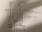
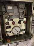
I am looking forward to see any a P&ID or a schematic that shows the valve position of Low lube oil header switch and transmitter arrangement. see the attached picture of how it looks like. I am particularly after the position of porting valves. should both of them be closed during normal operation?
Any help would be much appreciated.
Attachments
-
 85.9 KB Views: 28