Help Me- I Get 10 Degree Celcius Deviation In Tia Portal V20

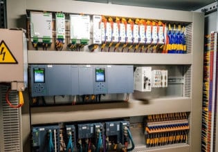
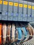
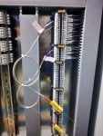
PlC Used- Siemns CPU 1512SP-PN
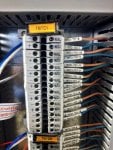
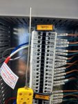
Thermocoule Type- K Type Thermocople Used
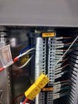
Thermocouple Card Used- 6ES7134-6JF00-0CA1
Thermocoule Card Bus Adapter- Siemens 6ES7193-6BP00-0DA1
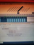
Used Compensation Method-1) Internal Reference Junction
2) Fixed Reference Junction
Eg-1)- Room Temperature is 27 Degree Celcius Then i got 370-400 Raw Value In tia portal watch Table
Dividing By 10 we get 37-40 almost 10 degree more
I tried lots of things by gudence os siemns online support you can check my PPT where i mentions my efforts to compensate this thing but still i didnt get solution .....
If any one have a idea please share ...I am wating for your Responses...
 

Attachments

Cold junction

You can't have both internal reference junction AND Fixed reference junction. One or the other.

You want Internal Reference Junction because that is continuous measurement of the cold junction reference temperature.
Fixed Reference is for metrology triple point icebath calibration or 1940's underground buried thermocouple reference junction technology.
 
It does not look like you have use the correct type of extension cable for a type K thermocouple.
Thanks for replying on this,
But we also tried to connect the Thermocouple on PLC TC card Channel directly ,but still we get 10 to 6 degree deviation in thermocouple reading and actual temp
 
@Sourabh Vathare,

If you have tried different T/C input cards and channels with the same T/C and you keep getting similar results then the problem is one of or a combination of these possible causes:

1) Incorrect T/C extension cable between the problem T/C and the input terminals. Each type of T/C requires a specific type of cable to be used to get the signal between the T/C tip and the input terminals of the monitor or PLC if the T/C can't be connected directly to the monitor/PLC. Type K T/Cs require Type K thermocouple extension wire--that is the two conductors of the cable are the same materials as the T/C itself--in this case, Chromel and Alumel. You can use any wire to connect the T/C to the monitor/PLC BUT the reading isn't going to be correct. You must use the proper type of wire to connect the T/C to the monitor/PLC if the T/C can't be directly connected to the monitor/PLC.

2) Incorrect terminations between the T/C and the monitor/PLC. While T/Cs seem to be simple, two-wire devices they develop the signal which is proportional to the temperature being measured because of the interaction between the two dissimilar metals. If ALL intermediate terminations of the T/C extension cable aren't made correctly then a small error will be introduced in the signal. For a Type K T/C this means that the Chromel conductors must be terminated to each other AND the Alumel conductors must be terminated to each other at every termination in the circuit between the T/C leads and the monitor/PLC input terminals (and the wires must also be connected to the proper monitor/PLC input terminals also!). This topic has been covered MANY times before on Control.com, with some ASCII text code drawings to demonstrate exactly how the terminations should be made. If there is any misconnection anywhere along the circuit then a small error will be introduced (and the error is a function of the temperature in the area where the misconnection is located). Use your preferred World Wide Web search engine to look up how to connect T/Cs using T/C extension wire to a monitor/PLC. It may SEEM simple (just two wires!) but it's NOT as simple as it seems and if it's not done correctly all along the circuit between the T/C and the monitor/PLC it is ultimately connected to then that's going to introduce an error.

3) Faulty T/C. If you connect the same T/C to different monitor/PLC input channels/terminals and keep getting the same error--then it would seem that the problem is the T/C itself. This does happen, but not very often. It could even be that the T/C was not installed correctly at the location where it is located, or that it was damaged during installation or it's simply NOT the type of T/C indicated on the data sheet which came with the T/C.

4) A problem with the thermowell or the way the T/C is inserted into the area where the temperature is being monitored.

5) You mentioned two different types of compensation which can be selected at the monitor/PLC. Only ONE type of compensation can be used per input. Perhaps you meant to say you tried both types of compensation for this particular problem T/C and had faulty readings, but that's not the way it was written and you haven't clarified the situation (whether one or both types of compensation were/are being used). (Frankly, I would find it difficult to believe the monitor/PLC would allow both types to be selected/enabled, but stranger things have happened.)

I was once at a site where the start-up/commissioning activity was extremely late because of problems with the mechanical assembly. Unbeknownst to me the electrician crew ran out of Type K thermocouple extension wire, and because it was a two-conductor cable they used some copper twisted, shielded cables for the last six or eight T/C inputs. And, that caused a great deal of consternation and head-scratching while trying to find out what the problem was. The electrician crew was really just trying to help get everything connected so that when the mechanical crew was finished we could proceed quickly with commissioning and return the equipment to the Customer. They were EXTREMELY conscientious people and they could make an incredible amount of terminations per hour--more than any crew I ever worked with in over 40 years! But, wire isn't always just wire--in this case the wire HAD TO BE Type K thermocouple extension, and copper wasn't suitable for the application. They apologized profusely and we had some t/C extension wire delivered the next day and they removed and terminated the correct T/C extension wire so fast it didn't seem possible--but that solved the problem with those inputs.

T/Cs are one of the only control elements/devices that require specific cable AND specific termination practices. Most every other electrical control element can use copper wire--but NOT T/Cs. AND, even if the correct T/C extension wire is used--it still has to be terminated correctly along the entire circuit between the T/C and the monitor/PLC input terminals to avoid just this type of error you seem to be describing.

If the monitor/PLC input channels/cards are working correctly EXCEPT WHEN THE PROBLEM T/C IS CONNECTED then it's either a T/C issue, an extension wire mismatch, some problem with any intermediate termination between the T/C itself and the monitor/PLC, or the way the T/C is mounted or installed. If the monitor/PLC input channels/cards are all working correctly UNTIL the problem T/C is connected to one of the inputs then it's NOT the monitor/PLC.

From the photos it appears that there is some kind of marshaling cabinet between the field wiring and the monitor/PLC terminals. It could even be that for this one particular T/C circuit the wrong type of T/C extension wire was used between the marshaling cabinet terminals and the monitor/PLC input terminals, or the wiring wasn't terminated correctly (Chromel was connected to Alumel and Alumel was connected to Chromel--something like that). It could be that the Chromel/Alumel terminal block itself is bad.

You can make a crude T/C by stripping the insulation from the two conductors of a short length of a Type K extension cable and twisting the wires together and then taking a hammer and smashing the bare, twisted wires together--just one firm strike is all it takes (put the bare, twisted wires on a vise or anvil and strike them with a hammer). Then strip the insulation off the other ends of the T/C extension wire and terminate them to the terminals in the marshaling cabinet terminals of the problem T/C and see what happens to that monitor/PLC input channel's reading. The makeshift T/C will be measuring the temperature of the air inside the marshaling cabinet so that's what should be displayed (if the correct compensation method is chosen on the monitor/PLC). If the reading is totally incorrect and you are sure of the correct termination of the makeshift T/C in the marshaling cabinet, then it's either the terminal blocks or the type of T/C extension cable between the marshaling cabinet terminals and the monitor/PLC input terminals.

As you can see, there are many possibilities for problems with T/C measurements--and it's only TWO wires!!! So, check methodically and carefully the entire circuit, including terminal blocks. Use the makeshift T/C and connect it to the T/C extension wire instead of the problem T/C and see what happens (it should display the air temperature in the area where the terminals are located). You can even use a heat gun or source of some sort to see what happens when the air temperature around the "tip" of the makeshift T/C changes.

If you have a T/C simulator you can try that as well in place of the problem T/C.

There are lots of things you can do--but thinking the problem is the monitor/PLC if you connect the problem T/C to different input channels/cards and the problem "follows" the problem T/C is not going to solve the problem. It's highly likely there is some kind of problem with the wiring and/or terminations or the T/C or the way it's mounted/installed or the type of compensation being used.

That's about it!

Look up thermocouple extension wire practices/methods to get a good understanding of what the problem(s) might be with a "simple" two wire device circuit.

And write back to let us know what you find and how your resolve the problem.
 
Top