How calculate combustion spread

No; the calculation works with "all" values. It's whether or not the values are correct for the application, and that will determine how spreads are detected and what happens when they are detected.

And, all Control Constants are not always the same for every Frame size GE-design heavy duty gas turbine. Many are, but sometimes Constants for functions like these are not the same. And, since GE Belfort was likely involved at some point with this unit (a 6FA) we can presume there are differences--some subtle, and some not so subtle.

I agree--the values of Control Constants should be confirmed with the packager if there is any question. But, we don't know a LOT about this situation. Has the unit previously run on gas fuel? Is this the first time the unit has run on gas fuel? Were there spread issues before this outage which are causing concern? Is this a new unit--or a unit being retrofitted to run natural gas, or some new gas with possibly different heating content?

Patience, sir. Patience is a virtue. And, Control.com is a good place to learn patience. It can also be frustrating if you don't have any. We will hear back if and when the poster decides it's beneficial to post feedback. Some recognize the benefit of posting feedback to others; most will only post feedback if they deem it's somehow beneficial to them personally to do so. All we can hope is that we encourage more of the latter to post feedback like the former--because that is the benefit to these World Wide Web forums.

BUT, we also have to realize--we are not always going to get feedback. Control.com is pretty unique in that, in my experience, more posters supply feedback than on a lot of other similar forums (fora, as some would have us refer to them!). But those that do provide feedback make this a really good site.
 
Great thanks CSA, I appreciate it, I don’t want to seem stupid and dull, could you tell me, what is on the picture, I highlighted it and what is the ttxspl_z1?
There is a missing value on the right side of the multiplier....

Looks like you got a customized software if it is really what is inside the "machine"

Lots of missing and not correct values ...i strongly suggest you to review the application code ...

Any time!

James
 
Soooo, here's an interpretation of the formula, in a pictorial format:

1619109135615.png

[CORRECTION: The output of the lower CLAMP block was shown with the incorrect value on original posting; it has been corrected to 38 deg C (the MIN limit of the CLAMP block). Sorry for any confusion!!!]

For the continuation, see below:

1619041136000.png

The Mark* value of 52 deg C is confirmed. I inserted the missing bits in the Item/Block Help pictorial representation (the two values of '0' that get passed to the calculation depending on the value of the logic permissives (L83SPO; L83SPMB)), and labeled the ramp block output with 'C' for clarity.

I tried writing the formula in a "mathematical" (algebraic) format, but that's very difficult with all of the signal names and the CLAMPs, etc.

The unlabeld block (the one with A/(1+ Bs) and the RESET=A in the box) is the block that adds a bias to the calculation, usually when load is being changed or when FSR is changing very quickly (see the logic for signal L83SPMB). This is done so as not to let momentary exhaust spreads (which I have NEVER seen) from causing nuisance alarms/trips. The block It also ramps the allowable spread value back down after the load change/FSR issue.

I have to admit; This is the first (maybe the second) time I've ever confirmed (verified) a value of TTXSPL.

It's not easy, and it's NOT like the formula the original poster wanted to use (the "easy" formula). One has to read the block and follow signals through the block. I always have to make a manual sketch of blocks like this because I can get easily confused trying to follow signals around, and it just makes it easier to be able to make sense of it (to me). (That's one of the really good things about Toolbox and the Mark V CSP--everything is in a graphical, relay ladder diagram format.)

Usually, inputs to a block are on the left side, and outputs of the block are on the right side (and this is true of elements inside the block as well--but just follow the lines). The only confusing part when learning this are the summing junction signals--which signal goes with which line. The signal to the right of a vertical line entering the summing junction from above indicates if the signal should be added or subtracted in the summing junction. The signal above a horizontal line going into the left of a summing junction indicates if the signal should be added or subtracted in the summing junction. The signal to the left of a line entering a summing junction from the bottom indicates whether the signal should be added or subtracted in the summing junction. The signal going out of a summing junction on the right side is almost always the output of the summing junction.

Hope this helps!
 

Attachments

Soooo, here's an interpretation of the formula, in a pictorial format:

View attachment 1199

For the continuation, see below:

View attachment 1201

The Mark* value of 52 deg C is confirmed. I inserted the missing bits in the Item/Block Help pictorial representation (the two values of '0' that get passed to the calculation depending on the value of the logic permissives (L83SPO; L83SPMB)), and labeled the ramp block output with 'C' for clarity.

I tried writing the formula in a "mathematical" (algebraic) format, but that's very difficult with all of the signal names and the CLAMPs, etc.

The unlabeld block (the one with A/(1+ Bs) and the RESET=A in the box) is the block that adds a bias to the calculation, usually when load is being changed or when FSR is changing very quickly (see the logic for signal L83SPMB). This is done so as not to let momentary exhaust spreads (which I have NEVER seen) from causing nuisance alarms/trips. The block It also ramps the allowable spread value back down after the load change/FSR issue.

I have to admit; This is the first (maybe the second) time I've ever confirmed (verified) a value of TTXSPL.

It's not easy, and it's NOT like the formula the original poster wanted to use (the "easy" formula). One has to read the block and follow signals through the block. I always have to make a manual sketch of blocks like this because I can get easily confused trying to follow signals around, and it just makes it easier to be able to make sense of it (to me). (That's one of the really good things about Toolbox and the Mark V CSP--everything is in a graphical, relay ladder diagram format.)

Usually, inputs to a block are on the left side, and outputs of the block are on the right side (and this is true of elements inside the block as well--but just follow the lines). The only confusing part when learning this are the summing junction signals--which signal goes with which line. The signal to the right of a vertical line entering the summing junction from above indicates if the signal should be added or subtracted in the summing junction. The signal above a horizontal line going into the left of a summing junction indicates if the signal should be added or subtracted in the summing junction. The signal to the left of a line entering a summing junction from the bottom indicates whether the signal should be added or subtracted in the summing junction. The signal going out of a summing junction on the right side is almost always the output of the summing junction.

Hope this helps!
After this discussion, i realize that it is really difficult to do calculation, and appearing exhaust spreads is cause troubles with fuel nozzles and other parts of combustion system. However, I appreciate your approach it and after first start up i will give information about values from real startup, now we have to solve problems with the fuel gas treatment unit(gas leackege, purging and etc.) and after resolution we will do first fire (i am going to record data with trend recorder it is great tool to solve problems and providing data for GE eng. support). Unfortunately we do not have CSP for this unit but it is FR5 Mark VIe DLN 2.5H(Florence). AND then IF I understand correctly Clamp MIN MAX It is LIMITS and selected value in this block, has to be between these limits???
 
The CLAMP block has MIN and MAX limits. The output of the block will be equal to the input IF the input value is neither greater than the MAX limit value nor less than the MIN limit value. If the input value is greater than the MAX limit value, then the output of the block will be equal to the MAX limit value. If the input value is less than the MIN limit value, then the output of the block will be equal to the MIN limit value.

I try to write my responses to cover many GE Mark* turbine control systems. Mark V uses CSP. Mark VI and -VIe use application code. Mark IV uses logic/sequencing. Really they are all just names for the same thing: The program which the turbine control runs to control and protect the unit and auxiliaries.

It is strongly recommended that you have GE Florence review the TTKSPLn Control Constants; all of them.

We look forward to hearing back from you. You can put a LOT of signals into a Trend file, and collect data for all the points. When you want to view only certain signal values, you can hide the signals you don't want to see, which makes it easier to review and analyze data. Hiding data points does not remove them from the file, so you can always unhide them later to view them and the data.

You can also export the information in the Trend file to a .csv (comma-separated value) file, and then attach that file to a post for us to review and analyze.

Best of luck with your first fire activities!
CSA please tell me, in case with + and - ,could you tell me what is the sequence, with what operand I have to start during calculation, I highlighted this on the screen.
What is the method of calculation in this case?
 

Attachments

The controls constants shown seems to not be correct as I mentionned on my previous post..

You got a messy situation over there...

A Thank you for you time and support would be greatly appreciated
..

You are almost welcome...

This thread is over for me as original poster is not replying with good manner...
Reread my posts... And recheck the combustion monitor controls constants

Adios amigos....
Hi hi, I have read all posts here thoroughly, but I can't understand, what happened with Constants because GE uses everywhere them for this unit , and there is no reason don't trust GE, from project to project it is not changed. Do you have a proof that constants aren't correct?
 
HI hi,

The CSP files and application code that I got showing not 14°c FOR EXAMPLE ON KSPLE8 for example ...Frame 9e IS 111°C

Frame 6B is about 95 °C

I may be wrong but it is always good to double check application code /controls constants in case....someting missed...it is not usual but again it can happen ....

The engineering units are wrong on some values ( do you need another proof )????!!!

We asked you some questions on that wrongs engineering units ...you did not reply....so for me thats not a way for solving issue ( if issue occuring)


Thx

Regards,
Controlsguy25.
 
And I am not sayin that GE (Nuvo pignogne /BAKER HUGHES/ whoever packaged the unit...) is wrong

Thats another story here ...something is missed ( "zero values " were not shown on block diagram that you posted...

What is value and engineering unit of TTKSPL4...

They were some mistakes and missing thing s on them so you just had read our comments and removed them without any Thank you for pointing .

Okay I udnerstood ! That will be not working for me
 
ControlEng999,

From post #23: “...The signal to the right of a vertical line entering the summing junction from above indicates if the signal should be added or subtracted in the summing junction. The signal above a horizontal line going into the left of a summing junction indicates if the signal should be added or subtracted in the summing junction. The signal to the left of a line entering a summing junction from the bottom indicates whether the signal should be added or subtracted in the summing junction. The signal going out of a summing junction on the right side is almost always the output of the summing junction.”

Perhaps if I have time today I will work on a picture to help explain it better.

When I was commissioning GE-design heavy duty gas turbines I would always do a quick review of Control Constants before every first fire. How did I do that? First, I would use the Control Specification to make sure what was in the Mark* matched what was in the Control Spec. For every single Control Constant. Takes a few hours and some concentration/focus, but it was always a good and useful task. I often found minor differences and corrected them. Occasionally I found major discrepancies which would have resulted in incorrect operation or worse which were corrected before STARTing the unit and having issues and then finding one or three Control Constants were not correct in the as-shipped Mark* software.

If something looked strange, I would look at values from previous start-ups and if it still didn’t seem correct I would contact the factory for clarification—and more than once was told to change the value, and I know had I not checked first that the unit would have had issues (alarming; tripping; failure to accelerate; excessively high acceleration; failure to fire; etc.).

Both ControlsGuy25 and I have strong suspicions about TTKSPLn values, and there’s no harm in asking for clarification. If you don’t ask now and have issues during commissioning later and need help in the middle of the night or on a holiday you’re going to be stuck, waiting. Not every unit is the same or uses the same Control Constant values but it’s also part of learning about the equipment and controls philosophies. We’re just trying to offer some observations, and you are not obligated to do anything with the information.

As for the missing information in the Item/Block Help description—that’s not your fault, ControlEng999–that’s some error with the drawing or the way it was displayed. Very odd, though because I have never seen those kind of almost glaring errors.

Anyway, I’m also looking for the GE descriptions of how to interpret summing junction operator symbols. I know exactly where to find it for Mark V, but not for Mark VIe.

Hope this helps!
 
And I am not sayin that GE (Nuvo pignogne /BAKER HUGHES/ whoever packaged the unit...) is wrong

Thats another story here ...something is missed ( "zero values " were not shown on block diagram that you posted...

What is value and engineering unit of TTKSPL4...

Also looks like HMI screenshots had just disappear by simply Magic Funny isnt it ???

They were some mistakes and missing thing s on them so you just had read our comments and removed them without any Thank you for pointing .

Okay I udnerstood ! That will be not working for me
Of course, it's very strange disappearing of this values, but I took this photo from HMI, GE didn't give anything like CSP, which can help to read this block, but maybe it is a part of their business, who knows
 
Of course, it's very strange disappearing of this values, but I took this photo from HMI, GE didn't give anything like CSP, which can help to read this block, but maybe it is a part of their business, who knows
I am also talking about HMI screenshots where we found mistakes ...not only the "0" missed in the TTXSPV4 block diagram
You stated that "GE didn't give anything like CSP" ...How are you going to operate this unit...

Usually GE delivers O&M manuals/documentation for the project...

Do you mean that you have no CSP file ...What is status of this unit... Commissioning /recommissioning

Lots of "we dont know on this case here..."

Thx for clarifying

So We can support you in a better manner/way
 
ControlEng999,

From post #23: “...The signal to the right of a vertical line entering the summing junction from above indicates if the signal should be added or subtracted in the summing junction. The signal above a horizontal line going into the left of a summing junction indicates if the signal should be added or subtracted in the summing junction. The signal to the left of a line entering a summing junction from the bottom indicates whether the signal should be added or subtracted in the summing junction. The signal going out of a summing junction on the right side is almost always the output of the summing junction.”

Perhaps if I have time today I will work on a picture to help explain it better.

When I was commissioning GE-design heavy duty gas turbines I would always do a quick review of Control Constants before every first fire. How did I do that? First, I would use the Control Specification to make sure what was in the Mark* matched what was in the Control Spec. For every single Control Constant. Takes a few hours and some concentration/focus, but it was always a good and useful task. I often found minor differences and corrected them. Occasionally I found major discrepancies which would have resulted in incorrect operation or worse which were corrected before STARTing the unit and having issues and then finding one or three Control Constants were not correct in the as-shipped Mark* software.

If something looked strange, I would look at values from previous start-ups and if it still didn’t seem correct I would contact the factory for clarification—and more than once was told to change the value, and I know had I not checked first that the unit would have had issues (alarming; tripping; failure to accelerate; excessively high acceleration; failure to fire; etc.).

Both ControlsGuy25 and I have strong suspicions about TTKSPLn values, and there’s no harm in asking for clarification. If you don’t ask now and have issues during commissioning later and need help in the middle of the night or on a holiday you’re going to be stuck, waiting. Not every unit is the same or uses the same Control Constant values but it’s also part of learning about the equipment and controls philosophies. We’re just trying to offer some observations, and you are not obligated to do anything with the information.

As for the missing information in the Item/Block Help description—that’s not your fault, ControlEng999–that’s some error with the drawing or the way it was displayed. Very odd, though because I have never seen those kind of almost glaring errors.

Anyway, I’m also looking for the GE descriptions of how to interpret summing junction operator symbols. I know exactly where to find it for Mark V, but not for Mark VIe.

Hope this helps!
Thanks CSA, as always you are right, and give great explanation, I really appreciate all guys here and their advice, but if the constants is not correct,the first fire will be unsuccessful, it will prove your presumption about wrong constants with ControlsGuy25.
We will see what we will see
 
I am also talking about HMI screenshots where we found mistakes ...not only the "0" missed in the TTXSPV4 block diagram
You stated that "GE didn't give anything like CSP" ...How are you going to operate this unit...

Usually GE delivers O&M manuals/documentation for the project...

Do you mean that you have no CSP file ...What is status of this unit... Commissioning /recommissioning

Lots of "we dont know on this case here..."

Thx for clarifying

So We can support you in a better manner/way
Commissioning phase of course, there is much information, but not csp.
 
Thanks CSA, as always you are right, and give great explanation, I really appreciate all guys here and their advice, but if the constants is not correct,the first fire will be unsuccessful, it will prove your presumption about wrong constants with ControlsGuy25.
We will see what we will see
I may be wrong but again it is always a good thing to check/recheck such controls constants
And specially when missing values or wrong engineering units have been discovered on at least the screenshots that you shared..
We are not at site to be able to check csp files.. So that's all we can do.. Remotely.. Advising you to get a good read on csp file according to our comments..

All the best for the commissioning phase /activities...


Cheers
James
Cheers
 
CSP, Control Sequence Program, refers to the program used to configure a Mark V turbine control panel to control and protect a unit and its auxiliaries.

With Mark VI and Mark VIe, GE decided to call the program 'application code.' It's the same thing--programming to make the control panel specific to a particular machine/site/application.

The CSP was printable, and the print-out was quite "easy" to read and interpret. Some CSPs require a ream of paper (500 sheets) to print out.

Application code is also printable, but it's NOT so easy to read and interpret--and printing the application code requires more than a ream of paper; it's huge. And, even though it's large (number of sheets) the printing on the sheets can be super small and difficult to read. GE presumes that NO ONE will print the application code, and EVERYONE will choose to simply look at the application code using Toolbox or ToolboxST on a large screen monitor.

Anyway, yes; if there are Control Constant values that are incorrect it will become evident during commissioning. ControlsGuy25 and I choose to try to eliminate as many problems during commissioning as possible because it just gives everyone a LOT more confidence in the equipment if there aren't a lot of problems. It's just a philosophical difference. And, of course, I understand if you're uncomfortable asking for clarification if you don't have a "good reason" to do so.

Best of luck!
 
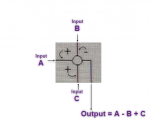
ControlEng999,

Here's some pictures which might help with understanding summing junctions--from your TTXSPV4 block question:

1619101972487.png

If you wish, you may consider associating the operation symbols ("+" and "-") with the input by finding a symbol and then look in an anti-clockwise fashion to the input. So, the subtraction operator ("-") above is associated with the input which is anti-clockwise to the symbol (Input B in the snippet above). Each of the two addition operators ("+") above are associated with the inputs which are located immediately clockwise to the operator symbol.

1619102508410.png
Same thing above--the input immediately anti-clockwise to the operator is the one the operator is associated with.

1619102330209.png
Same thing above, as well.

That's the GE Toolbox and ToolboxST convention for summing junctions in Item/Block Help--unless otherwise noted. Unless otherwise noted. With GE, there are exceptions to every rule (just like in life).

Hope this helps!
 

Attachments

ControlEng999,

Here's some pictures which might help with understanding summing junctions--from your TTXSPV4 block question:

View attachment 1208

If you wish, you may consider associating the operation symbols ("+" and "-") with the input by finding a symbol and then look in an anti-clockwise fashion to the input. So, the subtraction operator ("-") above is associated with the input which is anti-clockwise to the symbol (Input B in the snippet above). Each of the two addition operators ("+") above are associated with the inputs which are located immediately clockwise to the operator symbol.

View attachment 1211
Same thing above--the input immediately anti-clockwise to the operator is the one the operator is associated with.

View attachment 1210
Same thing above, as well.

That's the GE Toolbox and ToolboxST convention for summing junctions in Item/Block Help--unless otherwise noted. Unless otherwise noted. With GE, there are exceptions to every rule (just like in life).

Hope this helps!
Great thanks, just will be waiting for first fire guys, see you soon
 
Top