I observed that our purge valve is moving slowing.

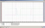
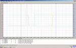
I observed that our purge valve is working slowing, When we stroke the valve, the movement is very slow compare to the other purge valve. The timing for mark VI is 8 seconds but more than 15 seconds. The purge valve is closing at 21 seconds there by causing the unit to run on Extended lean lean. What do you think that could be the cause???
 

Attachments

@EBUWAODUWA,

I only have access to the World Wide Web on my phone at the present time and I am unable to really see what is happening with any clarity. This is my problem and when I get a chance I will sit down at my workstation and have a proper look.

Your problem is, however, that you don’t share what has been done to troubleshoot the problem and that is terribly important—and frustrating.

Most of the gas fuel system purge valves are solenoid-operated pneumatically-actuated valves in a “double block and bleed” (back-to-back) arrangement with a small solenoid valve to vent any pressure between the valves when they are blocking purge air flow and with a pressure switch to monitor excessive valve leakage. Newer machines seem to be using electrically actuated valves but I don’t know how widespread that is or if electrically actuated valves are being widely used in this application now.

The typical problem with these valves is they have mechanically adjusted limit switches to detect fully open and fully closed positions and the Mark* monitors these limit switches to ensure the valves move to the positions they are commanded to move to.

Compressor discharge air is used as purge air for the gas fuel manifolds and nozzles. It’s very hot air and sometimes the limit switches are disturbed by the heat and pulsation.

Checking/Verifying the purge valve limit switch settings can really only be done when the machine is not running and when the piping and valves have cooled. The valves can be operated soon after shutdown but it’s dangerous for a human to be working on the valves and actuators when they are so hot. So, soon after the machine has reached zero speed and the gas fuel supply has been isolated the purge valves can be “stroked” to observe operation by a human from a safe distance (taking video is a really good idea) and the opening and closing times can be recorded while the valves are still very warm.

There is often a little “gotcha” with pneumatic actuators on GE-design heavy duty gas turbines. The air supply typically comes from compressor discharge and it can have lots of moisture in it (if the poro-stone filter isn’t working properly) and there are usually local pressure regulators for the gas fuel purge valves with little condensation bowls. The pressure regulators rarely, if ever, get the periodic maintenance they require or deserve to make sure the condensation bowls are working properly and clean and the air pressure regulators are adjusted to the proper pressure (which can affect actuation time).

So it may be necessary to arrange a source of CLEAN, DRY air for testing the gas fuel purge valves when the machine is on Cooldown…. Actually, many of us field engineers and some field service technicians strongly recommend installing an instrument air compressor to replace the compressor discharge air as pneumatic actuator supply as it is available 24/7 and it is easier to service. Wet air, which can also have rust particles from the cast steel poro-stone filter vessel, can cause a lot of problems for pneumatically actuated valves on GE-design heavy duty gas turbines—INCLUDING the compressor bleed valve actuators (which use unregulated compressor discharge air).

Adjusting the limit switches should ONLY be done after observation and determination they need to be adjusted. They need to be adjusted to change state at nearly full open or nearly full closed positions because if the valves leak there can be serious problems as a result. (Think gas fuel flowing into the compressor discharge-combustion wrapper and being ignited or burning in the combustion liners where it shouldn’t be burning.)

You also have a habit of not providing the Process Alarms annunciated when a problem occurs. We aren’t there alongside you seeing what you see and knowing what you know (and don’t know). You gotta tell us instead of us asking and finding out you’ve tried this or that already. I will tell you from my personal experience that I have traveled to sites where they haven’t been able to solve a problem with email or phone support and because of a lack of communication (even on the site) I have had to basically start from zero troubleshooting—only to be screamed at that, “We’ve DONE THAT ALREADY! You’re wasting our time and our money!” And I find out that either the tests weren’t done completely or they weren’t done at all.

In some cases it was a language problem; in others it was an almost violent belief that the Mark* was the sole source of the problem (usually because the Mechanical Department said so). In a few cases the troubleshooting methods caused damage to the Mark*, but of course that simply wasn’t possible (in their alternate reality).

You really will get better responses when you supply more information—especially when you tell us what you’ve done. And what the alarms are. We are grateful for the trends.
 
@EBUWAODUWA,

In some instances the gas fuel system purge valve actuators also have small "needle" valves in the actuator air supply lines and actuator air vent lines that are used to control the rate of opening and/or closing (to prevent sudden load fluctuations which can occur if the valves open or close too quickly). Many people think it's good fun to adjust these valves when they are standing around in the skid waiting for something to happen or to be told to do something. The needle valve opening can also be affected by moisture and dirty actuator supply air (yet ANOTHER VERY GOOD REASON for using a proper instrument air supply compressor/system to ensure the actuator air supply is CLEAN and DRY).

It has also occurred that these needle valves have been (mis)adjusted during "troubleshooting" problems just like the one you are reporting.

This is a really good time to mention the system P&ID drawings and how important (critical) they are to troubleshooting problems like this. They will show the devices (solenoids, needle valves, pressure regulators, limit switches, pressure switches, etc.) and this can be used to develop a check-list of things to verify are working properly--and correct if necessary. Sometimes the settings for the pressure regulators are shown in the NOTES section on the first page of the P&ID for a system; sometimes they are shown on the machine's Device Summary. The needle valves should have been adjusted during commissioning, but may need to be readjusted from time to time (though not usually if they are left undisturbed...).

So--lots of suggestions/recommendations to check on and verify. Learn to use the P&IDs when troubleshooting--they can be very, very helpful.
 
@EBUWAODUWA,

Again, I still haven't had time to look at the trend information you sent but I'm not clear if this is happening on BOTH of the gas fuel transfer purge valves or just one of them. Can you please clarify?

A couple more things about the source of air for pneumatically-operated valves on most GE-design heavy duty gas turbines. The poro-stone filter often appears on the Cooling & Sealing Air P&ID. It is usually located in the turbine compartment of GE-design Frame 7EA heavy duty gas turbines. It is fed by small tubing line connected to a threaded tap in the compressor discharge/combustion wrapper area and usually has a manual isolation valve which is supposed to be used to prevent Off-line Water Wash detergent and water from entering the poro-stone filter vessel. There is usually a short length of 1/8th pipe connected to a threaded connection on the bottom of the porostone filter, and there is usually a pipe cap on the end of the short pipe. There is a small hole drilled in the side of the pipe called a continuous blow-down orifice that allows a continuous flow of axial compressor discharge air to exit the poro-stone filter through the hole in the pipe. This is to ensure that most moisture that might collect in the poro-stone filter vessel from the axial compressor discharge air entering the poro-stone filter vessel cannot collect in the vessel.

The poro-stone filter vessel is made of cast steel--which means it can produce rust from the moisture entrained in the compressor discharge air flowing through the filter vessel and out of the continuous blow-down orifice. This rust usually drifts down into the small pipe and can block the continuous blow-down orifice so that no water can drain out of the poro-stone filter vessel, which caused more rust. This means water and rust particles can make their way to the pressure regulators and even the pneumatic valve actuators, causing problems.

Usually on the pressure regulator which controls the pressure of the air passing to the pneumatic valve actuator there is small, clear glass moisture separator bowl which collects water--and sometimes rust particles--and needs to be periodically drained (and this often gets overlooked or forgotten during maintenance outages). But, if there is water in the bowl, and rust flakes, that's a pretty good sign that the pressure regulator may be receiving water and contaminants causing it not to maintain the proper air pressure, and that water and contaminants are probably also making their way to the pneumatic actuator(s) which can cause problems for the actuators.

The poro-stone filter is easily opened (when the machine is not running) and inspected. You may have to replace the paper gasket at the top of the vessel after removing the cap. The poro-stone filter is just a piece of "rock" that looks porous like a piece of volcanic rock might look. It's purpose is to cause a great number of changes of direction for the air passing through it, hopefully causing any entrained moisture in the air to condense and fall down to the bottom of the vessel and exit through the open (unblocked) continuous blow-down orifice. Note that this air supply method (taking air from the axial compressor discharge and using to actuator valves) doesn't use a lot of air so the flows are not very large at any given time. This air source is often used for the compressor bleed valves and that is the biggest "consumer" of this air source; most of the other pneumatically-operated valves are much smaller and don't require nearly as much air, and don't operate very often, either. But, still the poro-stone filter is often a very overlooked but important element of this air supply source. As is the pressure regulators at the gas fuel purge valves.

One last thing--the pen width and the color of traces of a trend recording graph can be changed to be wider, even have different line styles as well as different colors. This can help GREATLY when examining a trend because the default pen widths and sometimes colors can be VERY difficult to find and follow on a trend recording. On some versions of Trend Recorder or Trender if one left-clicks on a data name in the list at the bottom of the trend the associated trend like will be changed (usually by widening the trace width) and it can be easier to see and follow. NONE of these changes will cause the loss of any data in a trend recording. Unnecessary data traces can even be "hidden" to remove them from the visual trend recording to make the recording easier to analyze--again, without deleting any of the data of the recording. Trend Recorder or Trender is an extremely powerful tool that is extremely underutilized because people just never feel comfortable manipulating or changing things. Learning to use Trend Recorder can make one a VERY valuable employee...! And, trend recordings of good starts are just as important as trend recordings of bad or failed starts--by having something to compare with or against. So, start getting familiar with Trend Recorder or Trender just recording normal STARTs and STOPs--the risk of filling up the HMI hard disk is very slim. And the more one uses and becomes familiar with Trend Recorder or Trender the more comfortable one is going to be using it when it's needed.

Trend recordings can be used to "catch" Mark* problems--but it can also be used to analyze devices and sequences outside of the Mark*'s control. Yes, the Mark* tells the gas fuel purge valves to open and close, but the rate at which that happens is not controlled by the Mark*--rather it's a function of the air pressure to the pneumatic actuators (also not controlled by the Mark*) and the pressure regulator operation (also not controlled by the Mark*) and the positions of the needle valves (if used and are also not controlled by the Mark*). If water and/or contaminants gets into those devices--including the solenoid valves used to allow or vent air pressure to/from the actuators--that can cause problems which the Mark* can't control or even detect, except when the valve's aren't opening/closing in the proper times.
 
Top