IEEE754 Floating points in Tridium

Hi All,
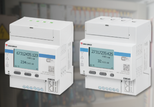
I'm trying to communicate with an Italian modbus energy meter (elcontrol sirio) it's using IEEE754 floating points in Tridium. It's telling me the energy register is at 0022/0023 (40022/40023) but I can't seem to get a valid response back. I've tried swapping the byte order around, been up and down a register and even tried it as a long type, but nothing works. The meter is also being polled by another system, Elcomponent MM software over TCP and it is polling the correct readings, that software seems to be polling input registers at 30020/30021. I've also tried these registers, they do return a value but nothing that makes sense, i've also tried math on the return values but to no avail.

I can get the correct value out from the meter if I change it's protocol to BCD and read individual enumerated bits, then remap them in the right order by using the Tridium expert math block to set the bits to the correct point in the meter index but this means changing the settings of over 150 meters and will prevent the other software from polling the meters correctly.

I've attached a copy of the modbus manual, if anyone is able to shed some light on how I could get the values from these meters I would very much appreciate the help.

TIA
Rich
 

Attachments

1. Input vs Holding Registers

The Modbus documentation has some factual errors with regards to Input vs Holding Registers.

Their use of the expression 40022 for a register address (page 8) is incorrect because the leading numeral 4 in the expression is a Modbus spec/convention that defines a Holding Register. They do correctly identify the Modbus Function Code 03 that is used to read Holding Register(s) on page 7 and Function Code 04 for read Input Register on page 8.

But as far as I can tell, this device uses Input Registers only, not Holding Registers, as described on both pages 8 (for RTU mode, top of the page Read Input Register (04H) and on page 22 for IEEE mode (at the top of the list, "Input Registers List for IEEE Format).

In quick summary, you can not read 40021/22 because those are Holding Registers and do not exist, as you've found out.

Their examples for reading Input Registers (page 8) and Holding Registers (page 7) in the RTU section incorrectly use addresses with the wrong leading numerals. They incorrectly use 40003 for an Input Register, which should be 30003, and incorrectly use 30003 for a Holding Register example, which should be 40003.

The only purpose of the leading numeral is to let human beings recognize the register address as either an Input Register, using leading numeral (3), or a Holding Register using leading numeral (4), because the leading numeral is NOT used in the Modbus message, it's there as an descriptive identifier. It is the associated Function Code that is used in the Modbus message that defines the memory area where the registers reside. (For reasons unexplained, the Modbus Spec generates confusion in general by identifying Input Registers, (3)xxxx, that use Function Code 04, and Holding Registers, (4)xxxx, that use Function Code 03. One would think the leading numeral would match the Function Code, but they've been swapped since the beginning of Modbus).

Given that the address register lists all are identified as Input Registers, you do not get a response when your master queries using Function Code 03 requesting Holding Register data because there are no Holding Registers. Your master needs to poll for Input Registers (FC 04), which as you've found, does return data.

2. Making sense of the data you can read from Input Register(s)

A. zero based versus one based register addressing

Programmers start counting from zero.
Ordinary people start counting from one.

The Modbus message uses zero based addressing because its binary. Addressing starts at 0000.
But for human readability purposes a register address using the leading numeral is usually listed using one based addressing

One based addressing looks like

(3)0001 value X
(3)0003 value Y
(3)0005 value Z

The same addressing as zero based would look like

0000 value x
0002 value y
0004 value z

The difference manifests itself in what I call the "one offset" problem.

The document addresses the one offset issue in their examples of calculating the address:

The address of the input register, to be used to request the data, is obtained by removing the function
code (e.g. “4”) and subtracting 1 from the register number itself, as shown on page 8.
E.g..: Reg. 40003 (in decimals) > 0003 (in decimals) > (0003 – 1) = 0002 (in decimals)

The example above says that 40003 (should be 30003 for an Input Register) is a one based address and the corresponding zero based address is 0002 (with no leading numeral, conforming to typical formatting for zero based addressing)

The Input Register list on pages 22 and 23 do not use the leading numeral, but appear to be one based addresses, starting at 0001

Masters differ in how one specifies target addressing. Some use the leading numeral to determine the associated function code. Others require one to specify the Function Code and then depending on implementation, either a one based address or a zero based address. Sometimes it isn't clear whether the address is one or zero based and experimentation is needed to find out.

B. Floating point formats

The document specs the format of the IEEE 'protocol' as Intel Little Endian

There are four word/byte order IEEE formats for 32 bit floating point. Most masters offer a choice of two of them.

Rather than trying to decode the bit pattern, which apparently you can do, I find it's usually easier to use the alternative FP interpretation that most Modbus master offer, although the choice to pick the alternative might be buried somewhere (I have to keep a note on where Kepware's OPC server hides it). The wrong word/byte order interpretation format will produce incredibly bogus values, like 8.08e-024 when the real value is 74.468.

Check the master for the choice of interpreting floating point formats.

C. All that said, you might have to do what we all have do at times: experiment to hit the exact register address.

When doing so, it pays to work with a register that has a known value (never a normal logic 0) or one that has a defined range that you know so that mis-reading an adjacent value that looks 'readable' does not throw you off the path.

For total active energy that is listed as 0021 adn 0022, I'd start by polling for two Input Registers, using Function Code 04h, starting at address (3)0021 and trying to interpret the data as either of the available FP formats until one makes sense and the other doesn't.

If neither produces a readable value, then try starting at address 0020.
 
Hi David,
Thanks for your reply. What you've said makes total sense, I've worked with hundreds of modbus meters and never come across a meter as difficult as this one. I've polled the registers as input registers and get some results back but nothing that makes any sense. Normally if i'm stuck with a meter I aim to get the frequency as it's almost always going to be 49Hz so it's a great register to focus on but even that is returning strange values.

I don't know enough about modbus to probe the meters further and I'm also limited to options of changing the byte order. I can swap between 3210 and 1032 and then swapping the register between holding/input and setting the format as integer, float, long or a signed integer.

3210 and 1032 I understand is the big endian - little endian but you mentioned there are 4 orders possible, so my thinking is that the devices are using one of the other formats possible. My reason for thinking this is that as I swap over between the 2 options and the register gets re-read it does sow up with the correct result for a few seconds (at least on the frequency register), I don't really have a question to reply with i'm just wondering if this would make sense to you?

Cheers
Rich
 
Have you tried all the start register values on either side of the target? (3)0019, (3)0020 and (3)0021 (3)0022

Reading only 2 registers?

Can you do a single shot poll rather than sequential polls or the polling way down to make sure the slave (or the master) isn't choking. I can't remember a master choking, but I've had a slave choke on too many polls too quickly.

Yes, the 3,2,1,0 and the 1,0,3,2 formats are the two common formats. I don't recall having run into one of the other two formats for Modbus. But that doesn't say that some device hasn't done it. The info below uses one based counting, so it's 4,3,2,1 or 2, 1, 4, 3, but it's the same concept.

01 Honeywell IEEE floating point format byte designation.jpg
02 Honeywell floating point formats.jpg

If it isn't one of those two, then what do you do? You already mentioned that the master has limited ability to band bits around to change the format.

There was discussion of using something like Red Lion's Data Station Plus, programmed with the Crimson 3 development software to act as a ASCII/RTU converter at some time in the past. The idea was to read the slave in one protocol (ASCII) as a master, convert the data to binary integer or FP formatted data, stick the new into a register that the master can read in as RTU or TCP data. It probably could be used to move the words and bytes around to get the 32 bits into the order the master can handle.

The Crimson software has these data manipulation instructions that could swap bytes and words to get it as needed.
format manipulation instructions for FP, ASCII or RTU formats.JPG

Last time I looked a Data Station Plus was $650-$800, depending on the model. Does the application warrant this kind of approach?

Maybe someone else has a suggestion.
 
Top