Making sense of a Modbus register

Hi guys,

I have kind of a noob question here, hope you guys don't mind.

I managed to extract some data using a VB.NET script from modbus device, where the data is just unsigned integers.

I used the "read holding registers" function in VB.NET to read the first 10 values.

Here's a snippet:
Code:
Dim regvals As Integer()
            regvals = ModC.ReadHoldingRegisters(0, 10)


            If regvals.Length > 0 Then
                ListBoxRegValues.Items.Clear()

                For Each value As Integer In regvals
                    ListBoxRegValues.Items.Add(value)

                Next

            End If
Now, the device's MODBUS communication address table is as follows:


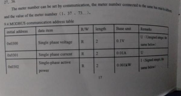
So, if I'm reading let's say:

13616
12576
20079
29728
.
.
.


Does this mean that the first value (13616) corresponds to the value in register 0x0300?

Many thanks to the gurus!
Vizier87
 
If your master/client poll started at address 0x0300, then the first reported 16 bit value is from 0x0300.

The question is which value is 0x0301?

The documentation is confusing.

The documentation's column labeled "length" states the value 2 for each of the registers. If length means the number of 16 bit registers, that would mean a 32 bit value occupying two adjacent, contiguous registers, for example: 0x0300 and 0x0301.

However the next stated value is in register 0x0301.

So I have to conclude that if the documentation follows Modbus convention, then the column labeled 'length' refers to the number of 8 bit bytes, not the number of 16 bit Modbus register words.
 
No, the Modbus protocol does not support exchange of address register numbers.

Does the value 1316.6 V make sense for the single phase voltage or 125.76 A for the single phase current?
 
No, the Modbus protocol does not support exchange of address register numbers.

Does the value 1316.6 V make sense for the single phase voltage or 125.76 A for the single phase current?
I see.

I think the web interface (which is supposed to be the front end to this gizmo) has some sort of multiplier/coefficient which then translates into domestic voltage values.

At this point I probably have to map the readings and compare them with the corresponding values from the web interface, which is going to be a pain in the neck.

I think you might be right, I might have to concatenate the values from the different registers and then try to make sense of the data.

Again, thank you very much for your response.
 
Hi Vizier87,
When trying to validate your data for the first time, you need something fairly solid as your target. Will your device give you the supply 'Frequency'? Depending on what country you're in, that's going to be very close to 50 or 60. If you can nail that down, you can build some confidence to work on the harder variables. As always with Modbus, good luck!
 
With some modbus devices you have to leave the byte order as MSB, swap the Words to LSB then copy that value into a float (real) tag. You may have to divide to get a float value from a Dint for example as modbus does not send decimal points.

So as said, in your manual it must be sending two bytes, so you may have to capture each byte then rotate the order so low byte first, then high byte last and see what value that gives. (I.e. your complete value is "low byte : high byte" as one value)

I had this issue with Spyder tension modules and got crazy values until I realised they were sending the words (in my case 32 bit = 2 x 16 bit words) in the opposite order to the way you would expect.
 
OK, I'll chime in here. This really doesn't need to be as complicated as everyone's making it seem.

Does this mean that the first value (13616) corresponds to the value in register 0x0300?
No, absolutely not!

In that post, you provided VB.NET code with this line:
regvals = ModC.ReadHoldingRegisters(0, 10)
This is reading Modbus register addresses 0 to 9, or in hexadecimal, 0x000 to 0x0009 (using 0-based addressing)

The device's Modbus table shows addresses 0x0300 to 0x0302. Reading registers 0x0000 to 0x0009 is not the same as reading registers 0x0300 to 0x0302.

The code above should instead be as follows:
regvals = ModC.ReadHoldingRegisters(768, 3)
Note that 0x0300 is equal to 768 in decimal. This will read Modbus registers 0x0300 to 0x0302 from the device.

Run the code above and report the values that you read back and what the current Single phase voltage, Single phase current, and Single-phase active power are on the meter at the time of reading the Modbus values.
 
OK, I'll chime in here. This really doesn't need to be as complicated as everyone's making it seem.


No, absolutely not!

In that post, you provided VB.NET code with this line:
regvals = ModC.ReadHoldingRegisters(0, 10)
This is reading Modbus register addresses 0 to 9, or in hexadecimal, 0x000 to 0x0009 (using 0-based addressing)

The device's Modbus table shows addresses 0x0300 to 0x0302. Reading registers 0x0000 to 0x0009 is not the same as reading registers 0x0300 to 0x0302.

The code above should instead be as follows:
regvals = ModC.ReadHoldingRegisters(768, 3)
Note that 0x0300 is equal to 768 in decimal. This will read Modbus registers 0x0300 to 0x0302 from the device.

Run the code above and report the values that you read back and what the current Single phase voltage, Single phase current, and Single-phase active power are on the meter at the time of reading the Modbus values.

Hi everyone, I must thank you tremendously for your contributions. I wasn't expecting any further replies, but this is totally a nice surprise!

Ok lemme ruminate on these posts and I'll get back here ASAP.

Vizier87
 
Hi Vizier87,
I do not know how your meter is related to SDM120.
But in the past I read SDM120 input registers with IndigoSCADA.
I read Voltage, Current, Total active energy, Frequency.
They are all 32 bits floating point input registers with
swapped words.
Here is a doc about configuration of modbus driver:
http://www.enscada.com/a7khg9/SDM120_IndigoSCADA.pdf
Best regards,
Apa
EXACTLY what I said. Same experience here with Spyder tension meters and with PM500 power meters. 32 bit (double word) registers where the words have to be swapped over.
 
Hi everyone, many thanks for the replies.

The device I'm trying to read from is an Acrel ADF400L. Here's the manual but I'm afraid that's all they have.

Right now, I think something not right. Here are the values if I keyed in 0 to 10 as follows:
1.png

However, if I keyed in 768 (as per jschulze's suggestion) and try to read 10 values, the values are identical to the one in the former:

2.png

Is there something I'm missing?

Thanks!
 
I recommend trying a commercial Modbus master software tool such as ModScan, Simply Modbus, or Modbus Poll. Note, that some of these tools use 1-based Modbus register addressing, so you may need to add 1 to the register address (i.e. 769 instead of 768).

What are the expected values of the Single phase voltage, Single phase current, and Single-phase active power?

FWIW, I believe the following is an online version of the manual you took a picture of in your first post that includes the register listing:
https://cn.jsacrel.cn/uploads/soft/210607/2-21060G30154.pdf
Since the full register list shows registers with a length of 4 that use 2 register addresses, this almost definitively means that the length is in bytes. Therefore, registers with length 2 are standard 16-bit Modbus registers.

Hi Jschulze,

Thanks for the recommendation on the softwares! I'll look into it for sure.

Oh wow you found the manual! Yes it is the very same one with a hardcopy I have right now. Again, thanks!

But how do I explain getting the same 10 readings despite changing the "begin" addresses? Does this mean I have other issues I have to look into?

Thanks.
 
There could be a lot of reasons why you're seeing what you're seeing. One possible reason, which is why I recommended using commercial software, is there may be a bug or mistake in your VB program. I just noticed this now, but it seems you're trying to access port 80. Port 80 is for HTTP. The default Modbus/TCP port is 502. I'm very surprised you would be getting any Modbus values when targeting port 80.
 
Top