Modbus Slave ID help

Hi everyone,

I have some electrical background, however a newbie to Modbus. I have setup a small test project with 2 slave devices and a master device.

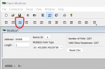
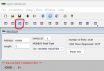
I am stuck on changing a slave device id from 1 to 2.

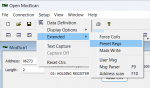
I am not clear on the vendor documentation (attached) which provides an example of changing the device id. page 2, The function code is 10H, which I cannot find, unfortunately the vendor does not speak english so is not helpful, other than provide the document.

I have also attached a document that lists my equipment, configuration and progress to date.

Can anyone review and point out where I am going wrong?

Cheers for now.
 

Attachments

The Modbus function code 10 hex (16 decimal) is used to write one or more 16 bit value(s) to Holding Registers by the Modbus master/client. The master needs to have that Modbus function 16 (decimal, 10 hex) implemented.

I can show how to first read the value, the write a value in Open Modscan, a Windows Modbus master app.

Open Modscan for Windows PCs is available here:
https://github.com/sanny32/OpenModScan/releases/tag/1.6.1

You'll need a USB/serial 485 or 232 converter, whichever the slave uses. I recommend one with an FTDI chipset. Check Device Manager for the COM port the converter installs on.

First, You need to connect to the slave device, using "Connection" and fill in the serial settings that must match the serial settings on the slave and COM port address for the USB serial converter.

Test your connection by having Open Modscan read hex address 57. But Open Modscan uses decimal, not hex, and it uses is one-based register numbering starting with number 1 (whereas hex numbering starts at zero).

So use FC03 (Read Holding Registers) to read register 88 (decimal). 57H = 87 (decimal) +1 = 88.

I don't have a device at slave ID 1, (or with a writeable register at (4)0088), so your screen should look something like the one below, but with your data (not mine) and the working area should report that the value at 40088 is the value 1, the actual slave node ID for that device:

Device ID (Unit ID/node address) = 1 (the slave you are connecting to)
register address = 00088
Click the 3rd button from the left, which is colored blue and highlighted in red. That will display data values as 16 bit integer values.
Modbus Point Type = 03: Holding Register

read register 88, as integer, highlighted 2.png

My screen says "Device Not Connected" because my device is not ID 1. That message disappears when the master connects to the slave.

Once the master connects and you can read the data at register 88, then you can change one of slaves to unit ID #2.

In Open Modscan, FC 16 is hidden pretty well. To use Function Code 16, navigate Setup > Extended > Preset Regs

01 Setup - Extended - Preset Regs.png

Don't use my value, use yours:
Slave device = 1
Address = 88
Number of Points = 1
Click OK
02 FC 16 (decimal) Force Multiple Registers.png

Type the value needed, in this case the value 2 for unit/node ID #2 in the correct cell, which should be the first one (+0, circled in red). Click OK. (Pay no attention to my register values or the value written, that's for the device on my bench).

03 enter the value in the correct cell for the appropriate register.png

Your working screen should then show that 40088 = integer value 2
 

Attachments

hi David,

thanks for your time and clear, helpful response.

I have now progressed to the final stage as below. After entering 2 I pressed OK, however did not see any change on my main screen. It was still talking and receiving responses from the slave with id =1. Not sure what I missed.
Cheers
1727641797212.png
 
What you are looking at is the date/time stamped 'Traffic' display. It exercises your hexadecimal language skills.

Change to 'Data' display:
Setup > Display Options > Show Data
 
Ok, I revised the display to Show Data and repeated the previous sequence.

1727650603560.png1727650651103.png Select OK


return to this screen which has the same values, I would have expected comms to cease as the device id should be 2 and I would need to change it from 1 to 2 to have comms??

1727650826716.png
 
Also, as the number of polls and valid slave responses match, is that sufficient to confirm the USB to 485 converter and wiring are correct, thus eliminated from possible troubles?

1727651203046.png
 
Yes, the continuing 'number of polls and 'valid slave responses' indicates continued successful communication.

It is my experience that most serial devices need to be power cycled before the device 'recognizes' a serial port setting change.

Yes, once the Device ID is changed, you'd have to change the Device ID value to establish communications.
 
Seeing as how the value you're successfully reading for register 40088 (hex address 0057) is a 0, instead of a 1 as expected, and that writing to that register has no effect, I would bet the register listing document you have is incorrect for the device you have.

The PDF you attached to your original post shows values using Modbus Poll at register addresses 32 (hex 0020) and 86 (hex 0056). Register 0020H is documented as the baud rate, but a value of 1 is not valid. If you're communicating at the default of 9600 baud, the value of register 0020H should be 6. Register 0056H is documented as the Single circuit power in units of 0.01% of the full current range of the device. So a Modbus value of 19 would equate to 0.19%.

Do any other registers have non-zero values? Does register 40087 (i.e. register address 86, hex 0056) show expected values when varying the current that the device is measuring?
 
Hi David, thanks for your confirmations, yes i did power cycle, no change

Hi jschulze, thanks for your input. From my growing understanding I have suspected the document supplied by the vendor is either generic or for other devices.

Please also note I have no wiring running thru the CT at this stage, so 0 current. Trying to keep it simple and just change the id.

Using Modpoll bus I have done a 999 scan of the holding register in dec mode and the following addresses hold a value other than 0

32=1
86= 17,18,19 & 20 repeated rolling values, refer to attached screen video (had to zip it as cannot upload video file).
288=1
342=18
544=1
598=20
800=1
854=18

It looks as if 86, 342 , 598 & 854 are the same, above just reflects the diffent times the snap value was taken.

On the chance address 32 was the device id, I then tried the previous exercise of changing the value of address 32 from 1 to 2. Recycled the power, no change

Would I be correct in believing the vendor would have a "list" of all registers/addresses they used to store data for this device?

If yes,what would be the best terminology to ask for this list?

cheers
 

Attachments

From your list, it seems to me that there are really only 2 registers with non-zero values: 32 and 86. The device may simply be masking/ignoring the upper 8 bits of the address (the "alias" registers are all multiples of 256 above those two registers).

Since register 86 seems to be randomly changing slightly, that may be the reading of the current going through the CT (essentially 0.18% means no current).

When you write to register 32, are you using function code 16 (write multiple registers) or function code 6 (write a single register)? Does it make any difference if you use the other function code? Does the value change after you write, or does it remain at a value of 1? Does ModScan/Modbus Poll show any errors when writing?

As you've no doubt found out, it is nearly impossible to use a Modbus device without knowing what data corresponds to which register numbers. Therefore, all Modbus device manufacturers must provide a Modbus register list for their device, detailing what data is mapped to which register numbers. This information is usually contained in the device's User's Manual, but sometimes manufacturers maintain a separate document or Excel spreadsheet for the latest Modbus register list.
 
With Modbuspoll, I have tried writing to reg 32 using Single Register
1727733359124.pngresult 1727733408566.png

and Multiple Register
1727733501194.pngresult 1727733550897.png

same timeout error.

Left field question, Do devices have a lock to prevent accidental change to values?

I have taken your description " Modbus device manufacturers must provide a Modbus register list for their device, detailing what data is mapped to which register numbers "
and a Chinese associate has translated to Chinese, which has been emailed to the vendor, I guess as a last resort.

fingers crossed

cheers
 
A properly implemented Modbus slave should always respond to valid requests (i.e. no CRC errors) addressed to its slave ID, even if it is an exception response stating that the requested function or register number is not supported. However, it seems this device simply does not respond at all (indicated by the timeout error you're seeing).

Now, I did notice you are trying to write 6 registers when you tried using function code 16. Does the write still timeout if you change the Quantity field to 1 and write only to register address 32?

Left field question, Do devices have a lock to prevent accidental change to values?
This is more of a vendor-specific, device implementation question. This would not be covered by Modbus specification, as the specification deals only in the low-level communication, not the high-level application considerations.

I have seen Modbus devices that do have locks, of sorts, whether it be implemented by requiring a password to be sent periodically, requiring the device to be in a certain mode, or setting parameter(s) on the device to allow commands from the network.
 
Top