null shift .CDP LM2500

Good afternoon, everyone.please help me with the situation.

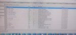
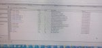
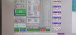
There is a misalignment(mismatch) between the target and the actual position on the CDP(compressor discharge pressure) valve.

Task 4% , position 13%.(minimum valve closure is 4%)

I think that the valve is closed, because according to the value of WB3, this is the flow rate through the valve (0.07 pps). After looking at historical trends, I saw that at 13% position, the flow rate is 10 times higher.(0.7 pps)

I see an null shift error in the alarm list.

a very important detail.when task(demand) above 13.5 %,(or higher) the actual position and task are compared

Can you tell me what actions can be taken?

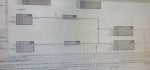
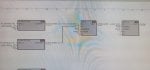
I attach a photo of the values and the logic from where they are formed.
I'm sorry for the English, I had to use a translator.
 

Attachments

You are getting the null shift alarm because the actual CDP position (CDPSEL = 13%) is not able to reach the demanded position (CDPDMD = 4%). When the actual position matches the demanded position the demanded current should be close the expected null current. When the actual position differs from the demanded position the current demanded by the control will differ from the null current. In your case, when the CDP current loop gain is multiplied by the CDP error (CDPERR) value of 9% stroke (13-4 = 9) the current demanded by the control exceeds the allowable difference (10 mA) from the expected null current (-20 mA) for the prescribed persistence time.

The first step I would do is recalibrate the CDP valve. It is possible that it is not calibrated correctly and reporting 13% position when it is hard against the mechanical stop which prevents any further movement. Recalibrating the valve should ensure that 0% position is hard closed against the stop. If you have data that includes the secondary coil voltages of the CDP valve from when it was working properly, you can compare that against the voltages that you are currently seeing. There should see a voltage difference between 0% (or 4%) and 13%. That should help you determine if the reported position is truly the actual position.

Other checks include ensuring the cabling, wires, and connectors in the CDP loop are clean, have continuity, are properly grounded, and functioning properly. Another check would be to open up the CDP pipe and examine the position of the butterfly to ensure that it moves freely and there is not a mechanical issue with the valve.

Hope this helps.
 
thanks for the reply.at the moment, the turbine is in operation and it is not possible to make your recommendations.On Friday, January 24th, we will have freezing temperatures of -28 degrees Celsius, and I expect the CDP to open.I want to record the trends of what will happen at this time.what will be the currents.
 
You are getting the null shift alarm because the actual CDP position (CDPSEL = 13%) is not able to reach the demanded position (CDPDMD = 4%). When the actual position matches the demanded position the demanded current should be close the expected null current. When the actual position differs from the demanded position the current demanded by the control will differ from the null current. In your case, when the CDP current loop gain is multiplied by the CDP error (CDPERR) value of 9% stroke (13-4 = 9) the current demanded by the control exceeds the allowable difference (10 mA) from the expected null current (-20 mA) for the prescribed persistence time.

The first step I would do is recalibrate the CDP valve. It is possible that it is not calibrated correctly and reporting 13% position when it is hard against the mechanical stop which prevents any further movement. Recalibrating the valve should ensure that 0% position is hard closed against the stop. If you have data that includes the secondary coil voltages of the CDP valve from when it was working properly, you can compare that against the voltages that you are currently seeing. There should see a voltage difference between 0% (or 4%) and 13%. That should help you determine if the reported position is truly the actual position.

Other checks include ensuring the cabling, wires, and connectors in the CDP loop are clean, have continuity, are properly grounded, and functioning properly. Another check would be to open up the CDP pipe and examine the position of the butterfly to ensure that it moves freely and there is not a mechanical issue with the valve.

Hope this helps.


Hello. and so, I came back with new data. as we can see, with an increase in the percentage of CDP opening, the valve setting and position are the same.When the valve is closed, it begins to diverge.
 

Attachments

Thus data looks good. Note:

1. CDPDMD and CDPSSEl are within 2% stroke of each other.

2. CDPA and CDPB are very close and consistent.

3. The demanded mA (CDPMA) is close to the null current of -20.

Given only this data I would believe that the cdp loop is working correctly. However we know the cdpsel cannot go lower than 13% from previous data.

I still suspect that either the cdp valve is miss-calibrated or there's some kind of mechanical interferrence preventing the valve from fully closing.

If the valve cannot fully close then the engine should be less efficient because it is doing work on the air and the releasing it through the cdp pipe before the engine can extract that work. You should see either a higher t48, less power, or more fuel flow at max load. If you have data at max load at the same ambient conditions (and similar fuel properties) from when the valve was known to be working properly, you should be able to compare t48, mw, and fuel flow and see a difference.

If the data matches then the valve is really closed and it is probably a calibration issue. If the t48, mw, or fuel flow are noticeably different for the same conditions the the cdp valve is probably open.

Also note that since the valve produces expected results at 18-19% stroke it is less likely (but not impossible) to be an electrical issue since you would not expect an electrical issue to only manifest itself at lower stroke positions.


and so the problem was solved, it was some kind of seal on the valve that had broken and was preventing the CDP from closing
we just cut it off, and you can see the remaining piece in the photo
 

Attachments

Top