Facebook
 Google
 GitHub
 Linkedin
Hi all,
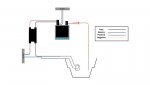
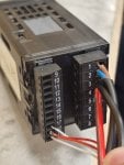
I have a Pixsys ATR244-12ABC temperature controller, and it’s connected as follows:
Pins 17/18/19 are connected to a PT100 temperature probe.
Pins 1 and 2 are connected to the AC 240V mains supply (to power the device).
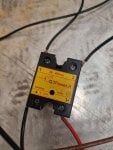
Pins 3 and 4 are connected to a solid-state relay (SSR), which has terminals labeled 3+ / 4- / 1 / 2:
Pin 4 of the ATR244 is connected to 3+ of the SSR with a red (positive) wire.
Pin 3 of the ATR244 is connected to 4- of the SSR with a black (negative) wire.
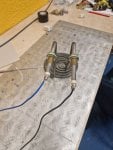
For the heating element wiring:
Terminal 1 of the SSR is connected to the live (phase) wire from the AC 230V supply using a black wire.
From the same AC socket, the neutral (blue) wire goes directly to one terminal of the heating element.
The other terminal of the heating element is connected to terminal 2 of the SSR with a black wire (phase).
The problem:
The controller correctly reads the temperature from the PT100 sensor — temperature changes are detected properly.
However, the heating element does not warm up at all.
Even when I set a target temperature (e.g., 50°C), the controller switches to C1 mode, and the TUN LED turns on, but the heating element remains cold.
I left it running for several minutes, and the temperature didn’t increase by even 0.1°C.
I can hear the relay click when it activates, so the control signal is definitely being sent.
My questions:
How can I make the heating element work?
What could be the cause of this issue?
Is this a wiring problem or a controller configuration issue (such as incorrect output settings on the ATR244)?
Thank you in advance
Best Regards
Francesco
I have a Pixsys ATR244-12ABC temperature controller, and it’s connected as follows:
Pins 17/18/19 are connected to a PT100 temperature probe.
Pins 1 and 2 are connected to the AC 240V mains supply (to power the device).
Pins 3 and 4 are connected to a solid-state relay (SSR), which has terminals labeled 3+ / 4- / 1 / 2:
Pin 4 of the ATR244 is connected to 3+ of the SSR with a red (positive) wire.
Pin 3 of the ATR244 is connected to 4- of the SSR with a black (negative) wire.
For the heating element wiring:
Terminal 1 of the SSR is connected to the live (phase) wire from the AC 230V supply using a black wire.
From the same AC socket, the neutral (blue) wire goes directly to one terminal of the heating element.
The other terminal of the heating element is connected to terminal 2 of the SSR with a black wire (phase).
The problem:
The controller correctly reads the temperature from the PT100 sensor — temperature changes are detected properly.
However, the heating element does not warm up at all.
Even when I set a target temperature (e.g., 50°C), the controller switches to C1 mode, and the TUN LED turns on, but the heating element remains cold.
I left it running for several minutes, and the temperature didn’t increase by even 0.1°C.
I can hear the relay click when it activates, so the control signal is definitely being sent.
My questions:
How can I make the heating element work?
What could be the cause of this issue?
Is this a wiring problem or a controller configuration issue (such as incorrect output settings on the ATR244)?
Thank you in advance
Best Regards
Francesco
Attachments
-
 16.8 KB Views: 5
 -
 88.4 KB Views: 7
 -
 144.2 KB Views: 11
 -
 85.6 KB Views: 10