Pressure and flow control at the same time

CONTROL STATION.jpg

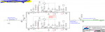
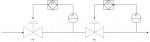
In our plant we have this pressure/ flow control station to maintain feed gas pressure and flow at required optimum values. I have a difficult time understanding how both of these controllers work at the same time. For example, if it is desired to increase the flow then the flow controller opens the flow control valve and as a result more flow will be obtained, however, the pressure will also increase the pressure upstream the flow control valve which in turn induces the pressure controller to open the pressure control valve to compensate for pressure decrease but this will lead to flow increase as well so the flow control valve shall close to maintain constant flow. How is the required steady flow and pressure is realized if adjustment in any valve will make the other valve close or open as well?! and what is the point of having such control configuration rather than having one valve?
 

Attachments

You may consider what appears to be 2 closed loop controllers each having a purpose which appears to be in conflict with the other. If you turn the flow controller 'off' then control would refer to the pressure controller and vice versa.

One suspects that rather than be in conflict, providing the flow and pressure setpoints are reasonable , there is no reason why both controllers cannot function in harmony even though the concept of individual valves / controllers demonstrate they are functioning separately.
 
Hi buddy,

In tight control applications a lead lag circuit may be provided in the logic and also there can be numerous variations in the way you want to design a control system. But the most efficient with the least cost involved is the one envisaged always. So yours would also work absolutely. I don't find any reason why it should not work. I can understand why you are thinking like this, its because both valves would try to control a single process and in doing so they would start to fight for it. Right, I understand your concern.
But just remember that for any control system to work properly and to provide a reasonable control the total loop gain of the system must be less than one. If the total loop gain reaches one, then the system would have an undamped oscillation and the fighting would never stop. So in the design phase, during design review, experienced engineers/managers takes care of the loop gain. Loop gain is a complex concept when it comes to modeling and predicting the toal loop gain of a system and honestly there are lot of reasons why it might increase or decrease after an installation. PID tuning is a very simple example by which we are actually changing the loop gain of the system. Hope this helps.
Cheers! :)
 
Hi,
Your two control loops should have a different dynamic response time not to fight each other.
If you are not too demanding about the accuracy of your pressure control, one way to achieve that would be to use a self contained pressure regulator instead of a pressure control loop, which should react to any disturbance much quicker than the flow control loop. Pressure control aims at relieving the flow loop from correcting upstream pressure variations, therefore enhancing its robustness.
 
I had that same installation on a Gas Control system. The pressure controller was at the Gas Yard and the Flow Controller was 7 miles away. This was on a 10 inch pipeline. The Set point on the Gas Pressure had another purpose also, to keep the Safety valves from relieving every time the units cycled off at night. The lines going to the Gas Turbines each also had Fisher Press Regulators on the lines. The 7 miles of pipe kept this thing from swinging very much due to Volume lag. Are both at your Facillity close together.? If so does it say anything about that setup being a Safety backup?? Just curious. Have a Good day..Bob
 
Science20,
Is this system in operation? Does it work properly? I'm interested in seeing the commanded valve positions of each valve and the process variable behavior. Can you share a trend plot of pressure, flow, and each valve's position?
 
Science20,
Is this system in operation? Does it work properly? I'm interested in seeing the commanded valve positions of each valve and the process variable behavior. Can you share a trend plot of pressure, flow, and each valve's position?
I've been Retired for almost 2 years.. February 7th, 2020. Don't have access to anything anymore except my memory of it thanks to NERC, FERC. Power Plant in Central, Florida.. Sorry, Bob
 
Top