Speed Sensor Spurious Values on Hydraulic Starting System

Hi Guys,


Just wondering if you guys may have come across a problem similar as below. Any suggestions are much appreciated.

Application Information:

LM2500 (2 of) → Hydraulic Starting System → Speed Sensors

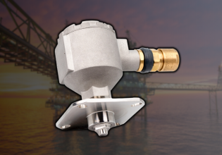
Speed Sensors = Honeywell 3090A

I/O Card = TREA Turbine Emergency Trip


We have two Passive Speed Sensors (77HS1/2) on our Hydraulic Starting System which continuously oscillate between 400 – 600RPM after the clutch has disengaged and the unit is online. When the unit is offline, both sensors read 0RPM as expected and during Startup the speed sensors respond as expected. Multiple modifications to the Air Gap and Resistor Networks have been made as per BH / GE without any success. Do you think this could be noise from when the machine is running? Shielding etc. has been checked too. This behavior is present on both units and the concern is that the sensors may reach the trip value of 900RPM, as they have done so once before.

Cheers
 
When did this problem start? Has it been ongoing since commissioning, or did it start months or years after commissioning?

The wiring for the speed pick-ups--how does it get from the pick-ups to the turbine control system? Does it pass through any conduit with high-voltage/high-current wiring (such as electric motor leads for the hydraulic starter)?

Many people don't understand how to properly use twisted, shielded pair wiring to get low-voltage signals from the field device to the control system/monitor. Proper grounding of the shield drain wires THROUGHOUT THE ENTIRE CIRCUIT is critical. There has been much written about this on Control.com. (Unfortunately, many of the "drawings" from years ago were done using ASCII text characters, and with the new system on Control.com they don't appear correctly now.)

If the machines have been running for some time it's possible that bearings are wearing out, allowing for shafts/rotors to "bounce" and appear to be rotating (this happens a lot with some versions of liquid fuel flow dividers). But it can happen with worn bearings or loose mounts or worn shafts.
Thank you for the reply.

The issues have been ongoing on both machines since commissioning. We can only make adjustments to the installation that are approved / recommended by the OEM. For this reason, it has been challenging to make any modifications as the process takes an extended time.

I've just arrived offshore and will be entering the enclosure tomorrow to make adjustments to the air gap and will carry out an inspection of the installation. From reviewing drawings / pictures, I can see that the sensors are each in a flexible conduit from the motor casing to a junction box. Between the junction box and the RIO (on-skid), they are in a conduit with some other signal wiring (see below).

LVDT's
Servo Valve Position Command
Other Passive Speed Sensors (NGG / NPT)

The sensor body is connected to ground. The shield is connected only at the Control Panel and floating at the device.
 
There's definitely something wrong with the routing of the cables.

There is more than likely at least one cable between each of the speed pick-ups and the Control Panel. And this is where the problem often comes in. The shield drain wire has to be in one of a couple possible configurations. IDEALLY, when there is more than one cable with a shield drain wires between the speed pick-up leads and the Control Panel the shield should be CONTINUOUS all the way through the circuit--and grounded ONLY AT ONE END (usually the Control Panel end). OR, if there are multiple cables with shield drain wires the shield drain wire of each length/section of cable should be grounded at ONE END ONLY. So, if there are three lengths of sheilded wire, each with a drain wire, the drain wire should be grounded at ONE end of each length of cable, and the other end of the shield drain wire for that length of cable should be properly cut off and taped to prevent inadvertent grounding. FOR EACH LENGTH OF CABLE BETWEEN THE SPEED PICK-UP LEADS AND THE CONTROL PANEL. SO, either the shield drain wire should be made continuous from the speed pick-up leads to the Control Panel, and terminated to ground in the Control Panel with the other end of the shield drain wire (in the junction box with the speed pick-up leads) cut off and taped to prevent inadvertent grounding. OR, the shield drain wire of each length of shielded cable should be terminated to ground AT ONE END ONLY with the other end cut off and taped to preven inadvertent grounding.

This next part can be the hard part. Because after assembly and construction sometimes it's very difficult to re-route cable and wires. low level signal wires (like speed pick-up wires) should NEVER be run in conduits or cable trays or cable trenches with high-voltage/high-current wiring. Full stop. Period. But it happens. It happens all too often when unskilled craft labor are left to their own devices to run and terminate wiring. There's a pretty easy test for this. Run a single length of cable temporarily from one of the speed pick-ups to the Control Panel. Along the floor, any way to make sure it's not in a conduit or cable tray/trench with high-level (voltage and current). And watch to see what happens the next time the machine is run. It's very common, and USUALLY fine, to mix some high- and low-level signals for a short distance in a Control Panel or cable area below or behind the Control Panel.

Another possible problems I've seen in hazardous environments is problems with current-limiting isolators. Yeah; they only have passive components--but even those can fail, sometimes in unexpected ways.

I can hear it now. This is a hazardous/explosive environment and no Danger Ranger is EVER going to sign off on this--even for a short test. Well, then start going through every junction box the signals pass through to see how they're routed, checking the drain wire terminations, and the signal levels of the other wires/cables in the conduits.

Some turbine control systems (the GE Mark* systems, for example) have a configuration that allows for extremely sensitive setting (which is WAY TOO sensitive for almost EVERY application on a piece of high-speed rotating equipment). Finding this setting involves "rooting around" in Toolbox/ToolboxST for the speed pick-up inputs configuration variables and if it's set to sensitive it should be set to UNSENSITIVE for most applications.

The aero engine group defines specific parameters for control and protection of the engine and LP turbine (but not always the LP turbine). The way the packager of the engine accomplishes that control and protection is left up to the packager (S&S; GE; etc.). This specifity ALMOST NEVER includes the starting means--since there are many possible types of starting means, and the control and protection of the starting means is left up to the manufacturer of the starting means and/or the packager of the aero engine and auxiliaries. So, you SHOULD NOT have problems with changing the setting/sensitivies of the starting means, since it most likely wasn't produced by the GE aero engine group.

But if this is specific to these two machines with this type of starter, you can pretty much bet that something is amiss with the wiring--it's just that it can be one, or sometimes, two or more, of several possibilities. Troubleshooting is often a process of elimination--meaning that one has to work through all the possibilities in a logical manner and eliminate those that are proven to be NOT the problem. Until the problem is found. Now, with some knowledge and skill and a little bit of luck one can choose which possibilities to check out first based on likelihood or ease of checking/eliminating.

A LOT of people read these threads, now and in the future. By sharing what your results are and how you solve the problem it will help many people, maybe not with exactly the same problem, but with similar problems using the methods and techniques you describe.

Best of luck. And don't forget: GE aero engine group does not usually specifically define how the starting means must be protected. Only what the starting means needs to do to start the engine.

Go forth and conquer!
 
Hi,
Your clutch shoud be Hilliard Isn't it? We already faced this issue before, also GE already aware about this issue, just follow the below steps when you instell the probe:
1,Thread into housing untill probe touche gear.
2, Back probe out 360°-480° then tighten locknut.
 
Top