understanding the scheme for control devices of gas turbine

Hello everyone!
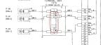
I have recently joined operation of an gas turbine power plant in india. GE make gas turbines are installed here (19.6 MW) with mark-VIe control system. I could acquire a drawing of "scheme for control devices", which is of course of a new project being underway. I need help to understand this drawing, which will help me in my operations. I thought this is the best forum for this. Please help....thanks
 

Attachments

jagriti,

The drawing you attached is an attempt at showing the relative locations of control devices on the gas turbine. The version you provided also refers to the GB (Load, or Reduction, Gear Box and the Generator).

It's only intended to demonstrate the relative positions (locations) of some of the total number of control devices provided with a complete gas turbine-generator package with auxiliaries--and in the case of this drawing, it's only the devices typically physically mounted on the turbine (left and right sides, and inlet and outlet (exhaust discharge) areas, with some added reference to some gear box and generator devices.

The thing you want to understand from studying the drawings is the signal names which are typically used to describe each of the various control devices, in addition to their location/position. If the unit (or units) are being constructed/installed and commissioned at this time, it's a VERY GOOD time to GET OUT to the unit and find as many of the control devices as you can--not just on the turbine, but also on the auxiliaries. It's very good to know where control devices are physically located when understanding and troubleshooting unit operation.

Hope this helps!!!
 
Thank you so much CSA for your time and help, yes it will help a lot.
I also want to understand the scheme for lube also, which i have attached herewith. Kindly help me to get some kind of write up of the whole process. It is better if you kindly can explain as it is more easier for us to understand.
regards
 

Attachments

jagriti,

The new unit should have been delivered with manuals, and in those manuals you should be able to find descriptions of each of the systems for which there is a P&ID. There is usually a tab in the manuals for each system, and that's more than likely where you found the P&ID (electronically or physically). That's the place to start trying to understand and learn each system: by reading the system descriptions. If you have questions, we can do our best to answer them here. But, do your homework and ask your questions.

I'm going to qualify my next statement by saying: I haven't looked at the L.O. P&ID you provided. But, IN GENERAL, it's helpful to know that lubricating oil is used for BOTH lubrication of bearings AND the hydraulic system fluid. You will hear the term "hydraulic system" and "hydraulic oil"--but it's typically the same fluid as the lubricating oil system uses. In fact, the hydraulic pumps are supplied with lubricating oil at their suction (inlet), and raise the pressure to hydraulic system pressure (usually around 1500 psig).

There should be an Auxiliary L.O. Pump (AC (Alternating Current) motor-driven); a Main L.O. Pump (Accessory Gear-driven, meaning the Main L.O. Pump is driven by the rotation of the turbine shaft); and a DC motor-driven Emergency L.O. Pump, used in case the Main L.O. Pump fails and the Aux. L.O. Pump is failed or unavailable. The purpose of the Emergency L.O. Pump is NOT to keep the unit running in the event of loss of the Main- and Aux. L.O. Pumps, but rather to supply L.O. flow and pressure to the bearings as the unit coasts down to zero speed. The Emergency L.O. Pump is then often cycled when the unit is at zero speed to keep a flow of oil to the bearings for cooling purposes.

As noted, the Main Hydraulic Pump, which is usually driven by the Accessory Gear (which is driven by the turbine shaft), is supplied with oil from either the discharge of the Main L.O. Pump or the Aux. L.O. Pump. Some units have an Auxiliary Hydraulic Pump, which is AC motor-driven.

When the turbine is started and reaches 100% speed, the Aux. L.O. Pump (used for starting the unit and during acceleration to rated speed) is shut down, and the Main Accessory Gear-driven L.O. Pump supplies the oil for the turbine bearings. If the unit has an Auxililary Hydraulic Pump, it is also used for starting and acceleration to rated speed, and is also shut down once the unit reaches rated speed. The idea is that turbine shaft power is to be used for normal running operation of both the Main L.O. Pump and the Main Hydraulic Pump. The Auxiliary Pumps are only to be run in the event of a problem with the Main Pumps. In fact, most generator drive GE-design Frame 5 heavy duty gas turbines cannot be synchronized if either or both the Aux. L.O. our Aux. Hyd. Pump is running.

There are filters and pressure regulators which require maintenance and periodic adjustment.

L.O. is also used for another hydraulic function: Control Oil. There should be a System Description for the Control Oil system, also.

Hope this helps!
 
Yes sir, thanks a lot. Actually physical manual not available to us. Kindly inform
(1) the difference of Main LO pump and Main hydraulic pump...their function/purpose, point of suction and where it all delivers oil at what pressure. What will happen (operation of the turbine ) if the Main LO pump or Main hydraulic pump develops less pressure then required ?
(2) Suction point of Aux LO pump and where it all delivers oil at what pressure. What will happen if the Aux LO pump develops less pressure then required ?
(3) Similar point as (2) for Emergency lube oil.

sorry for asking these silly questions as an operator
 
jagriti,

I can see apparently we are going to have to do this the harder way. But, first, do you have access to the electronic version of the manuals?

It is unforgivable that Operations Supervisors and Plant Managers withhold access to Operations and Maintenance Manuals from anyone in the plant. Ever. But, unfortunately, it happens all too often.

The Aux. L.O. Pump is at area F6 on the drawing. It is driven by motor 88QA, sometimes identified as 88QA-1. Just to the right of the Aux. L.O. Pump suction is the suction for the Main L.O. Pump; you have to follow the line from the Main L.O. Pump suction up to the<aim L.O. Pump on the Accessory Gear Box.

The Main Hydraulic Pump is NOT shown on this drawing; it is a variable, positive displacement, axial piston pump, driven by the Accessory Gear mechanism. The Main L.O. Pump is a positive displacement gear pump, driven by the Accessory Gear mechanism.

The suction of the Main Hyd. Pump is fed by (supplied by) the discharge of the L.O. Pumps; it is not capable of drawing oil from the L.O. tank.

As was described in the previous reply, the purpose of the L.O. pumps is to supply the bearings of the turbine, generator and Accessory Gear Box with lubricating oil. In addition, the L.O. Pumps also supply the Control Oil (sometimes referred to as the Trip Oil) system as well as supplying the suction of the Hyd. Pump(s). Find the two lines labeled OR1 and OR3 to see how the L. O. System and the Hydraulic System are connected. Note that the L.O. system also supplied oil to the Starting Means system.

The purpose of the Hyd. Pump(s) is to supply oil at a much higher pressure for use in controlling the positions of the fuel control valve (s), the fuel stop valve(s) and the variable Inlet Guide Vanes (which are used to control the air entering the axial compressor of the unit).

If the pumps don't deliver oil at the proper pressure (and flow-rate) then usually one or more Process Alarms will be annunciated, and if the pressure continues to decrease then the turbine will be tripped. Both are true of the L.O. Pumps, and while low hydraulic pressure will cause a Process Alarm, usually a really low hydraulic pressure does not cause the turbine control system to initiate a unit trip, but because the fuel valves will not stay open without hydraulic pressure the unit will trip because of insufficient fuel flow.

If the Main L.O. Pump has failed and the Aux. L.O. Pump is incapable of supplying oil at the necessary pressure, the unit will be tripped. And the Emergency L.O. Pump will supply lubricating oil as the unit coasts down to zero speed.

As you can see, the suctions of both the Main- and Aux. L.O. Pumps are at the same level in the L.O. tank. The suction of the Emergency L.O. Pump is at a slightly lower level.

I would like you to explain why the Emergency L.O. Pump suction is at a slightly lower level than the Main- and Aux. L.O. Pumps. (This is not a trick question; it's simply to let you participate in this learning.)

GE P&IDs are very simple, among the simplest on the planet. You have chosen to start with the system with the most components--which was your choice. But it's just ”busier” with more lines and components and information than any other P&ID, not any more complicated. If you want to be a good operator you need to study and understand the P&IDs; they are essential and critical to safe and efficient operation and troubleshooting.

You may not realize it--yet--but your most important kid as an Operator is ... Alarm Management. And that requires a good understanding of and familiarization of all the P&IDs. You may think, or you may have been told, that the Instrument & Control technicians or the Maintenance technicians will troubleshoot alarms. But a good operator that understands the P&IDs and can quickly respond to alarms can keep the unit running or prevent serious damage before most I&C it Maintenance technicians can get to the Control Room. And to be a good technician (I&C or Maintenance) one has to be a good operator, or at least know what's supposed to happen when (and what's not supposed to happen when!)

It takes time and experience, which is made shorter and easier with proper training. (And I'm NOT referring to ”on-the-job” training where supposedly ”experienced” people try to train or teach people with little or no experience. Many people are simply not good teachers, and their answers to many questions are, ”Because we've always done it that way,” or, ”That's the same problem as last time.” Those are the two WORST answers to questions--EVER.

Hope this helps!
 
Hello CSA and Control Team,
Please I have a quick question. In the drawing attached , it appears the deceleration solenoid(20DA-1),acceleration solenoid(20DA-2) and stop solenoid(20DV-1) are connected. Is the assumption correct that one terminal from the three devices are jumpered together and if so, why was is done?
 

Attachments

Yes. All solenoids share a common voltage, -125 VDC, usually identified as wire number (108).

That is normal. Using a single wire for a common voltage and jumpering it to multiple devices reduces the number of wires required. Electrically, it's exactly the same as using, in this case, three individual wires from the turbine control system.

Hope this helps!
 
Top