Facebook
 Google
 GitHub
 Linkedin
Hi for all;
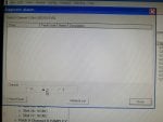
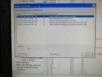
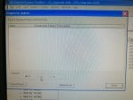
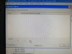
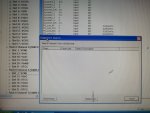
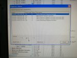
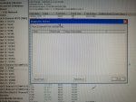
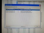
We have a gas turbine GE frame 9FA Mark6 control system. sometimes unit tripping by R and S offline processor alarm. we chearched so many times to
idintify why this alarm trigger and trip the machine but unfortunatly we not able to figgure out the problem. we suspected
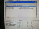
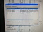
fail or malfunction in VCMI cards we replaced bothe VCMI cards and also control cards UCVG for both racks and run unit again after somtimes it repeated and unit tripped again. in SOE an alarm CPU SWITCHED SUSSPEND and Mark VI DALMLOG Report "IONET-2 Communications Failure" and Mark VI DALMLOG Report "IONET-3 Communications Failure" and before this both alarms one alarm Mark VI DALMLOG Report <Card reboot occurred here.>. we suspected again over voltage comming from DACA1,DACA2 and 125VDC battery Charger we measured volt and foun as follow 240,250 and 125 and found in range.again we do extra job take both cards VCMI and UCVG cards for three racks R,S and T and clean racks by blower and clean also IONET-1,2,3 socket and cables and start unit. it is run for some days and again tripped by same alarm. friends can any one face same issue and figure out the problem .
Thanks and best Regards
We have a gas turbine GE frame 9FA Mark6 control system. sometimes unit tripping by R and S offline processor alarm. we chearched so many times to
idintify why this alarm trigger and trip the machine but unfortunatly we not able to figgure out the problem. we suspected
fail or malfunction in VCMI cards we replaced bothe VCMI cards and also control cards UCVG for both racks and run unit again after somtimes it repeated and unit tripped again. in SOE an alarm CPU SWITCHED SUSSPEND and Mark VI DALMLOG Report "IONET-2 Communications Failure" and Mark VI DALMLOG Report "IONET-3 Communications Failure" and before this both alarms one alarm Mark VI DALMLOG Report <Card reboot occurred here.>. we suspected again over voltage comming from DACA1,DACA2 and 125VDC battery Charger we measured volt and foun as follow 240,250 and 125 and found in range.again we do extra job take both cards VCMI and UCVG cards for three racks R,S and T and clean racks by blower and clean also IONET-1,2,3 socket and cables and start unit. it is run for some days and again tripped by same alarm. friends can any one face same issue and figure out the problem .
Thanks and best Regards