Facebook
 Google
 GitHub
 Linkedin
An Introduction to Simultaneous Localization and Mapping (SLAM) for Robots
SLAM for robotics utilizes mapping and localization for accurate movement. This article covers the architecture of a mobile robot running SLAM and the different broad classifications withing SLAM.
Simultaneous localization and mapping (SLAM) is the standard technique for autonomous navigation of mobile robots and self-driving cars in an unknown environment. A lot of robotic research goes into SLAM to develop robust systems for self-driving cars, last-mile delivery robots, security robots, warehouse management, and disaster-relief robots.
This article is an overview of SLAM, covering the architecture of a mobile robot running SLAM and the different broad classifications of SLAM. Mobile robots can be wheel-based, biologically-inspired bipeds and quadrupeds, drones, and hybrids. However, this series of articles on SLAM limits the scope to wheel-based mobile robots only.
What is SLAM?
As the name suggests, SLAM comprises mapping and localization. It is used for outdoor and indoor navigation in environments with sufficient landmarks, distinct features, and navigable terrain. SLAM’s process involves a robot simultaneously creating and updating real-time maps of its environment while navigating the same and also locating its own position with respect to the map.

Figure 1. Autonomous robot navigation pipeline
Noisy environments, high-dimensionality, and correspondence are some outstanding challenges for robust SLAM solutions. The most common applications of SLAM include the deployment of robots in unexplored environments like disaster sites, underwater, extra-terrestrial locations, and more.
SLAM is a highly stochastic process as all the computations and results are expressed as probabilities, which ideally converge over time and, with a repeated exploration of the world, create stable values.
When navigating autonomously through an unknown environment, the robot keeps a track of its estimated (probabilistic) pose with reference to a global static frame usually located at its start point or a previous pose frame. Using its sensing mechanisms, it also interprets the world around it and creates a probabilistic representation of the constituent elements with respect to a fixed global frame of reference.
The complete autonomous robot navigation stack comprises localization, cognition, control, and perception stacks. Each of these contributes to a successful SLAM implementation.
Robot control refers to executing motion based on the intent of the system. In simpler terms, it ensures that the robot does (tracks a trajectory/stops/makes a zero-turn) what it is instructed to. Cognition is responsible for generating the desired tasks for the robot. It may involve breaking down the high-level tasks (like robot vacuum cleaning the floor) into simpler floor area decomposition and robot motion planning sub-tasks.
Utilizing SLAM With Autonomous Mobile Robots
Mobile robots need extensive hardware, on-board sensing, compute power, and accessories to support SLAM. All robot drive types (holonomic, Ackerman, or different drive) are suitable for SLAM, and, ideally, the powered wheel motors have encoder-based feedback.
A standard mobile robot has a chassis with wheels for motion. Each individual wheel motion contributes to the desired motion for the complete robot. The forward direction along the central longitudinal axis of the robot is called the heading. The center of the robot is the origin of the robot local frame and all its poses are defined for this point. The angle that the heading/X-axis of the local frame makes with the global frame X-axis is called the orientation.
Different drive mechanisms have different kinematic models and control inputs. For instance, a differential drive or a holonomic drive robot needs a velocity command for each wheel, while an Ackerman drive needs the throttle and steering angle inputs. The relationship between the control inputs and the Cartesian pose of a robot is called forward kinematics while inverse kinematics is the other way round.

Figure 2. Differential drive robot kinematic diagram (ICC stands for instantaneous center of curvature).
Sensor Suite for Mobile Robots
Sensors are used to measure the robot’s own pose as well as interpret the environment and objects within, to create a map of the same. Sensors are responsible to implement closed-loop feedback for control as well as safety features.
Poor sensor quality, noisy measurements, and inaccurate robot models exacerbate the stochasticity in SLAM. Thus, the mobile robot sensor suite ideally has redundant sensors for each type of measurement. The two broad categories of onboard sensors are interoceptive and exteroceptive. Interoceptive sensors measure different physical parameters of the robot itself while exteroceptive sensors interpret different aspects of the external world. Note that we are only covering sensors relevant to SLAM in this article.
Interoceptive Sensors
Interoceptive sensors may measure scalar or vector quantities. The most common interoceptive sensors include:
- Wheel Encoders: Wheel encoders measure the wheel rotations. Optical encoders have low resolution and perform satisfactorily for robot wheels but prone to ambient lighting and packaging issues. High-resolution and robust hall-effect encoders are the most used in the industry.
- Accelerometer: An accelerometer measures the linear acceleration of the robot along the Cartesian axes. It is usually a MEMS-based sensor that operates on a damped-mass and spring principle. An accelerometer’s provided acceleration is integrated to derive position and velocity information which makes it prone to bias.
- Gyroscope: A gyroscope measures the angular velocity of the chassis along the x, y, and z axes. It is a three orthogonally mounted gimbal system. The angular velocity is integrated to derive the orientation of the robot chassis. This orientation is used for other frame-based measurements and terrain information.
- GNSS: Global Navigation Satellite System (GNSS) is the generic system for the collection of satellites used for geo-spatial positioning. GPS and GLONASS are the specific implementations of GNSS used to localize the robot on the Earth’s longitude and latitude. GPS — the US-specific GNSS system — and similar systems have an accuracy of 3-10 meters for civilian applications and are usually deployed on outdoor robot navigation.
An IMU is a packaged accelerometer, gyroscope, and magnetometer. The sensor information is fused together in the IMU to obtain odometry information for the robot. This is the standard packaging used instead of the individual constituent sensors. Indoor environments are called GPS-denied locations which pose more challenges for SLAM
Exteroceptive Sensors
Exteroceptive sensors are more intricate and sensitive systems that involve extensive computations. Representation of the environment in a computer-interpretable format is the most challenging aspect of these sensors. Common exteroceptive sensors are:
- Range Sensors: Range sensors are a wide category of sensors that measure the distance from the robot to an obstacle in all directions. There are two popular types: RADAR and LiDAR. RADARs are responsible for long-range small-field of view range sensing. LiDARs, on the other hand, measure distance in all directions but do not have ranges as long as a RADAR. Two-dimensional LiDARs measure ranges in a plane while three-dimensional LiDARs measure the same in all radial directions. LiDARs have high operational speeds and, using minuscule angular intervals and a huge number of points, their information is used to create surfaces and distances from obstacles. Their data is usually represented as point cloud data. Other less popular range sensors like SONAR and IR sensors also exist but have limited performance and operational features. All these range sensors work on different principles like time-of-flight (ToF) or phase shifts to compute the distances.
- Cameras: Cameras are the most versatile sensors mounted on mobile robots. Standard RGB cameras are used to know the presence of different objects and their 2D location in the image canvas. Stereo-cameras provide depth-sensing as well and are used for obstacle avoidance, predictions, and more. Visual odometry estimation, obstacle classification for motion prediction, and free-path detection are some of the techniques dependent on cameras for autonomous navigation. Applications of depth cameras are similar to LiDARs but their performance is prone to ambient lighting conditions and are computationally more expensive as well. AI and deep learning algorithms are extensively used to compensate for all inaccuracies and limitations.


Figure 3. The Intel Realsense d435i Depth Camera (Image Source: Intel Realsense Website) and RPLiDAR A3 (Image Source: RPLiDAR A3 Website)
Such sensors used along with various perception algorithms, data fusion techniques, and time synchronization methods ensure accurate SLAM implementation and address the various probabilistic aspects of the problem.
Different SLAM Techniques
Based on the primary sensor used, type of information processing, and types of maps processed and generated, there are several classifications of SLAM.
Full SLAM and Online SLAM
Full SLAM and online SLAM are two categories based on the type of map and pose information on the process derives.
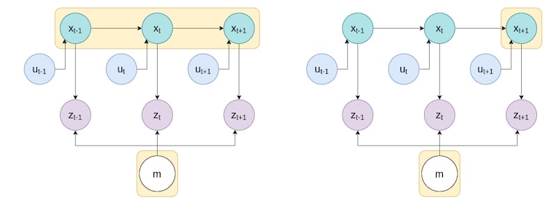
Figure 4. Full SLAM derives the complete sequence of robot poses, while online SLAM derives only the latest robot pose.
Full SLAM computes the complete set of poses over discrete time-steps from start until the current timestamp, along with the map of the environment. It is very computationally expensive (both in memory use and time) as it re-computes the complete sequence of robot poses i.e., the path.
Online SLAM is a subset of the above and only computes the current robot pose. All computations are done recursively and several algorithms are used to update previous measurements due to loop-closure or other significant events.
Visual SLAM and Rangefinder-based SLAM
Based on the type of sensor primarily used for exteroception, there are two broad categories: one uses computer vision, and the other one uses rangefinders.
Visual SLAM utilizes the feed from a camera to implement SLAM. There are several sub-types of visual SLAM depending on the type of camera and the processing done on them. MonoSLAM uses a single camera for real-time SLAM while RGB-D SLAM uses depth information along with RGB images to interpret the environment as well as derive the robot’s odometry.
Vision-based 3D feature maps used in sparse or dense SLAM utilize subsets of feature pixels or the complete image and extensive features respectively. Dense SLAM is computationally expensive but very rich in information and ensures developing highly accurate solutions.
EKF SLAM uses extended Kalman filters on LiDAR rangefinders for autonomous navigation. It involves landmark detection, data association, several EKF steps in localization, obtaining several covariance matrices for the relation between the variables, and finally recursive Bayesian updates to efficiently localize and map the environment. UKF SLAM is another similar approach using rangefinders but with the Unscented Kalman filter which approximates the distribution more appropriately using sigma points. FastSLAM uses a Particle filter and is more efficient than the previous two.
Review of SLAM and Next Steps
SLAM is a huge field and comprehensively discussing all its aspects is overwhelming. Defining the objectives and involved tasks for each smaller problem within SLAM is vital towards creating a feasible SLAM solution.
The next article in this series formulates SLAM for computational interpretation and explains mapping and localization in depth. Since SLAM is a vast field, it is important to know the extent and challenges of all sub-domains and only pick relevant ones for the system to solve.