Facebook
 Google
 GitHub
 Linkedin
Analog and Digital Signal Filtering in PLC Systems
Unexpected, false, and fluctuating PLC input signals can cost many hours of debugging, but luckily, there are some quick, simple tricks to try before downtime is wasted.
Today’s PLC processors are much faster than their predecessors from previous decades. Typically, a fast processor is desired to ensure that the logic can respond quickly to changing events in your equipment, but if your sensor signals flicker due to disturbances within the equipment, you might have unexpected data transfers or unexpected motion.
When this situation arises, which can happen with analog or digital signals, we need to either slow down the input signal frequency or filter the incoming signals.
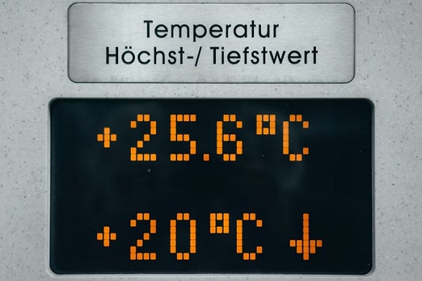
Figure 1. A display from an analog sensor showing the current temperature reading. Image used courtesy of Unsplash
Analog Signals
An analog sensor outputs a voltage or current that changes in accordance with process variables such as temperature or pressure. An amplifier is often used to filter and boost the signal, but it is still susceptible to electromagnetic fields when the signal is traveling between the amplifier and the input module, and these fields can cause disturbances in the signal. This noise can often be detected as a false reading or a jittering display.
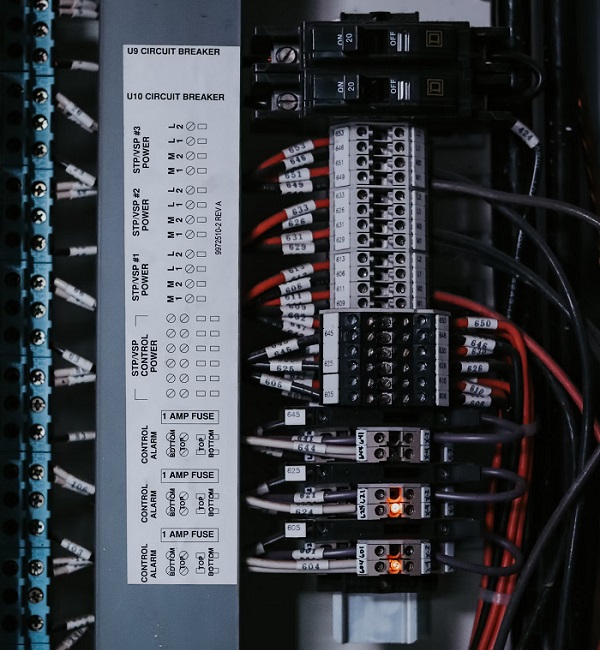
Figure 2. Control wiring for digital signals. Image used courtesy of Unsplash
Digital Signals
Digital signals can similarly be influenced by inductive equipment disturbances, which could cause false triggering of outputs, especially if you are using 5 VDC control voltage. A proximity sensor uses eddy currents to detect objects. Each material has a slightly different detecting range with a proximity sensor, so if the object you are trying to detect has different materials (or even surface finishes), you might detect something you don’t want to.
Pallets often use metal screws as ‘pallet present’ flags, wherein a proximity sensor detects the screw and alerts the PLC that a pallet is in place. If the flag is mounted onto an aluminum pallet, you might pick up the pallet instead of the flag, which would cause the pallet logic to go true a bit too early.
Filtering
There are a couple of ways of filtering your input to reduce false signals, and the type of signal you are using will depend heavily on your solution.
The first step is to resolve the issue that is causing the false signal in the first place. With analog voltage inputs, use short wire runs, keep high-frequency signal wires out of the same duct as analog wires, add a signal filter between the amplifier and the input module, or use a digital signal converter.
Digital signals will require investigation into the application of the sensor. Light sensors, such as through beam or diffused prox sensors, can be sensitive to stray reflections. Proximity sensors can pick up mounting materials or other materials from the surrounding area. Use shielded proximity sensors when possible, and ensure that objects used with light sensors are blocking a significant amount of ambient environment light from the sensor.
If you have exhausted all the physical solutions and you are still getting dirty signals, you might need to look into the PLC program.
Software Input Filtering
Most PLCs that offer analog inputs will also include an option for an input filter for each channel, or it might be a blanket setting for the entire input module. The input filter will slow down the sampling rate of the input, or it will reject any signal over a specific frequency, essentially smoothing out the incoming signal. While this method is effective, it will likely require downloading to the controller with every change.
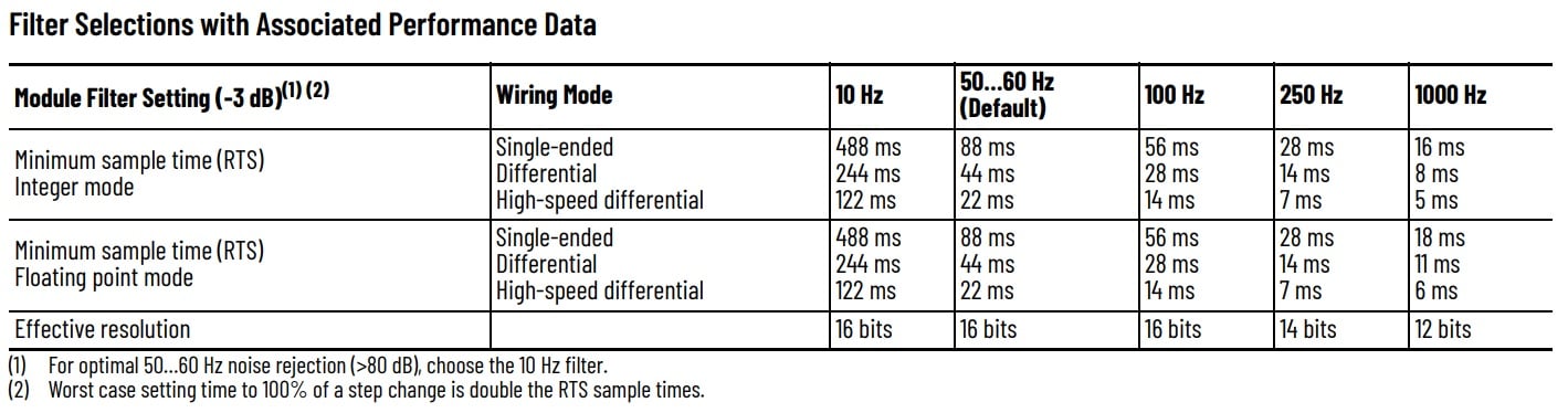
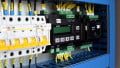
Figure 3. For this certain PLC analog input, settings are applied to the entire module. Also, note that a higher-frequency filter allows faster signal sample times. Image used courtesy of Rockwell Automation
If you want to filter only one analog input channel, or if you can’t constantly download new module configuration data to the controller, you can instead fill an array with input values every PLC cycle (or any interval you choose), then use a moving average to smooth out the overall value. As the values in the array change, the overall value will change with it.
The Debounce Timer
For digital signals, there might not be a configuration setting to filter out frequencies, but a common approach is to put in a debounce timer. A debounce timer requires the input to be in the True state for a specific amount of time before allowing the rest of the logic to be solved. Some PLC software includes debounce timers as a built-in command or setting in the input module, but they can also be created with one simple TON.
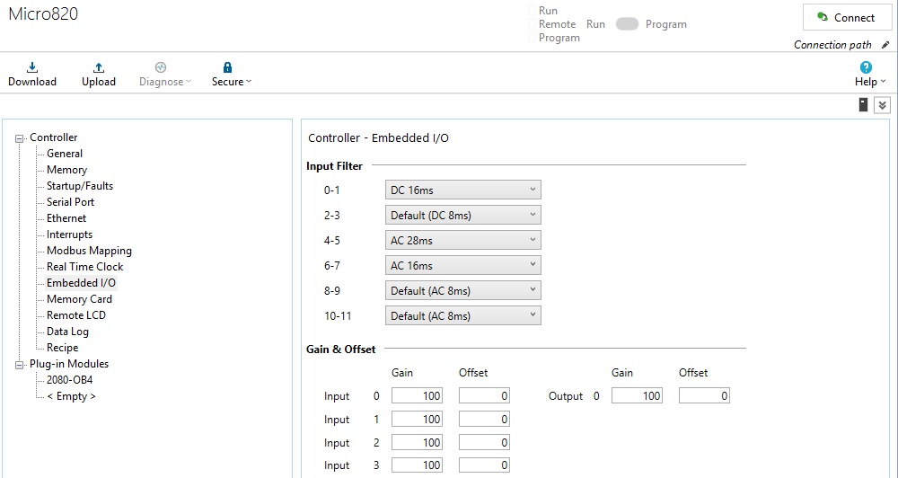
Figure 3. Screenshot of CCW input filter configuration. Image used courtesy of the author
These debounce timers are helpful in conveyor logic or part detection applications when any inconsistent orientation of parts can cause a momentary flicker when a part is entering or exiting the sensor view. The timer can easily be adjusted without downloading to the PLC, and the logic is very simple to implement.

Figure 4. An example of a debounce timer that delays the internal memory bit by 100 ms. Image used courtesy of the author
Troubleshooting and Investigation
Each method will require an in-depth investigation into the problem at hand. It is common to quickly add a debounce timer to digital inputs that are causing unexpected results, but try to take a minute and investigate the real problem. Analog signals are sensitive to wiring paths and any high-frequency equipment. Always check the cable path for analog sensor wires and adjust them as necessary.
Fluctuating analog signals and false pulses from digital sensors are known to send technicians on wild goose chases trying to find the reason, but sometimes, the solution is simply to just slow the PLC down a bit and allow some settling time.
Related Content