Facebook
 Google
 GitHub
 Linkedin
Explaining User-Defined Data Types for PLC Programming
User-defined data types (UDTs) are a powerful and useful tool when applied to their full advantage. However, misused, they can become problematic and introduce roadblocks to troubleshooting and upgrading PLC programs.
Within every computer program or PLC program reference document, you are certain to find some mention of elements known as "data types.”
PLC Standard Data Types
A data type is a method used to define one or more groups of memory within a computer program. The standard data types are integers (ranging from 8 to 64 bits in length), floating point numbers, boolean, charters, and strings.
According to the IEC 61131 standard, PLC technology takes this convention a few steps further and defines standardized names for single and double integers, signed and unsigned integers, timers, counters, strings, and finally, a data type that is made up of custom combinations of the above data types called a user-defined type, or a UDT.
Custom User-Defined Data Types (UDTs)
Similar to a “property” class in C programming, PLCs can create custom data types that are a combination of the standard data types. These UDTs can then be assigned to groupings of tags in the PLC.
The purpose of the UDT is to make scattered tag lists more compact and easier to read. A UDT also helps users find heavy use in repetitive code, such as station logic or robot communications. While UDTs are useful, they can be misused, especially when over-applied to simple applications. In this case, rendering multiple, complex tag layers and routines that become almost impossible to search and interpret.

Figure 1. Nearly every PLC IDE allows the programmer to create UDTs. Image used courtesy of Adobe Stock
Creating a UDT in a PLC
Every PLC manufacturer is slightly different, but invariably, somewhere in the code editor will be a place where you can create your UDT. Creating a UDT is relatively simple, but does require plenty of forethought and structure planning.
With Rockwell Automation’s Studio 5000 Logix Designer as an example, tags in the UDT should always be ordered from smallest data size to largest. The reason for this process has to do with how the software allocates memory for the different data types. Logix Designer will allocate more memory to larger data types such as timers, strings, and other large standard structure tags if they are structured near the top of the UDT.
Consider the following example to illustrate: with smaller data types at the bottom, the software will round up to the nearest byte. The following images show two UDTs with the exact same tags but arranged from smallest to largest (top), versus somewhat scattered (bottom). Note the data type size of each, outlined in red. Arranged in order leads to the most efficient size.

Figure 2. Efficiently designed UDT with the smallest tags at the top. Image used courtesy of the author

Figure 3. Poorly designed UDT with the tags in a more randomized size order. Image used courtesy of the author
UDTs with a large number of BOOL tags will also produce a larger total-sized UDT. This has to do with how Rockwell (and really, any computer) allocates memory for single-bit data types. Each Boolean tag takes up one address, which is 32 bits long, even though it is only one bit in useful size. If you made a UDT with only one bool, the size of that UDT would still be 32 bits (4 bytes), while the remainder of that memory is wasted space.
Sizing And Nesting UDTs
Most PLCs will allow nested UDTs, meaning you can create a UDT that contains other UDT tags within it. As you can imagine, this can potentially make for some very complex data types, but it can also greatly reduce your tag database.
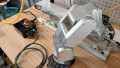
For example, imagine a pneumatic pick and place station which consists of a horizontal and vertical pneumatic cylinder along with a gripper. It might make sense to develop the following UDTs for communication and I/O:
- One UDT for the station control
- One UDT for HMI controls of the cylinders
- One UDT each for mapping the input sensors and output solenoids of the cylinders
All of these UDTs could be put into one UDT so that all of the tags for that station would take up the space of one tag in the tag database.

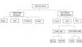
Figure 4. One UDT tag consisting of 4x nested UDTs, each performing a dedicated function. Image used courtesy of the author
At first glance, this solution may look like a great idea, but what if you wanted to search for a specific HMI tag? The search would come up with nothing because searching a tag database will only search the root tag name.
Another challenge resulting from embedding multiple tags is the appearance of very long tag names. If you wanted to address the input sensor for the cylinder above, it might look something like this: “PickPlaceStn.i.vertical.inputs.extended.” That’s a fairly long tag name for one input.

Figure 5. It’s important to remember that modern PLCs can control vast processes, so consolidation of data and room for expansion are parallel considerations. Image used courtesy of Adobe Stock
Proper Form and Function for UDTs
In light of those previous disadvantages, what is the best/correct way to make a UDT?
Unfortunately for the field of engineering, that is an open and debated question, so there really is no single right or wrong answer. Keep in mind that most PLCs will require a download or reinitialization if a UDT is changed. This could pose a problem if you need to make a change while the equipment is running.
From my own experience, I prefer to divide UDTs into major functions. That means one UDT for my station control, one for each Ethernet device, such as robots or cameras, and finally, a dedicated UDT for all the station inputs and all the station outputs.
The thought process behind this method recognizes that because the tags for the device are unlikely to change, it makes sense to consolidate them into a UDT. The station control logic shouldn’t really change after the code is debugged and commissioned, and even robot communications don’t change much after integration.
No Need to Brood Over Nesting UDTs
As for nesting UDTs, I try to only nest one layer deep. When I make a robot UDT, I’ll have the local control bits in the root, then I’ll have an input tag and an output UDT tag, each of which gets copied out to the Ethernet module. This also helps with future expansion into multiple robot systems, each subsequent robot can use the same control bits while customizing the mapping bits.

Figure 6. The organization of UDTs can help to not only make the program easier to read but also enable future expansion when adding new components. Image used courtesy of the author
Practical Application of UDTs
User-defined data types are a simple yet very important part of custom machine design. Well-designed UDTs can alleviate memory allocation and controller tag organization problems, but care must be taken to avoid using them haphazardly.
In the end, try not to have any more than two layers of UDTs and structure them to reduce unnecessary memory wastage when possible. This approach will produce clean, easy-to-read tags, easily searchable in your PLC.