Facebook
 Google
 GitHub
 Linkedin
How To: Using Set/Reset Instructions in Mitsubishi’s MELSEC PLCs
Setting and resetting a PLC output is essential in establishing a holding circuit for a transducer. Learn how to use set/reset instructions in MELSOFT series GX Works2 to latch and release an output.
Set/Reset, also known as latch/unlatch, is used in programmable logic controllers (PLCs) to control the output status based on specific input conditions. The concept is used in holding the condition of an output after a momentary input is triggered once, such as energizing a motor starter or indicator light. These inputs can be from sensors or momentary switches like push buttons. In this tutorial, we are going to explore how set/reset ladder logic is represented in MELSECs series PLCs using MELSOFT GX developer or GX Works 2.
Set/Reset Instruction Syntax
The instruction syntax for implementing the set/reset ladder may vary depending on the PLC type or the programming software. In MELSEC series PLCs, this instruction follows a specific syntax with a defined pattern. To set an output, the instruction mnemonic is represented by the word ‘SET’ for the latching function and ‘RST’ for reset, the unlatching function. These mnemonics are followed by the PLC I/O address or internal memory element to be set or reset.
Practical Programming Examples of Set/Reset
To get started with examples, we need to have GX Developer or GX Works 2 installed. For this tutorial, we are going to use GX Works 2. Once we have the software installed, we can open it and create a new project.
Assuming we have an output coil and two momentary switches S1 and S2 as our start and stop push buttons respectively, we can implement set/reset in two distinct ways in GX Works2. One of the ways we can do this is by implementing a latching circuit in a ladder program that latches the output. For this tutorial, we are going to use address Y000 for our output. For our input switches S1 and S2, we are going to use X000 and X001, respectively.
Three-wire Latching Circuit Example
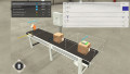
To implement a latching ladder logic program, we start the ladder with a normally open (N.O.) contact S1 to represent our start button and a normally closed (N.C.) contact S2 for stop. The output Y000 is latched as an N.O. OR branch to provide an alternative path for power to flow when the momentary switch S1 is released.

Figure 1. The output status is ON when the momentary start push button S1 is pressed and released.
When the N.C. stop switch S2 is pressed, the contact between the N.O. contact Y000 (latch) and the output Y000 is broken, thereby changing the output status to OFF.

Figure 2. The output status, Y000 is OFF after pressing S2.
SET/RST Latching Circuit Example
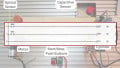
Another way in which letch/unlatch can be implemented is by using the SET/RST syntax. With the same PLC addresses, the ladder can be represented as shown in Figure 3. To set Y000, the contact S1 is used with its output being an application instruction found in the toolbar of the GX Works software. The application instruction is represented by the symbol -| |-. Once the application instruction is clicked, the syntax ‘SET Y000’ is fed into the text box.
To reset Y000, the input S2 is added to a new rung as an N.O. contact, and application instruction is selected to add the syntax ‘RST Y000’.

Figure 3. Momentary switches S1 and S2 are used to SET or RESET output Y000.
Resetting Timers and Counters
Timers and counters are special case applications where set/reset can be implemented. In timers, the reset instruction is used to reset the elapsed time to zero while in counters to reset the number of counts to zero. In this way, the RST instruction forces an address to become a zero value, which will de-energize a bit address, but will reset a timer or counter, all with the same instruction.
To practically demonstrate how resetting a timer and a counter works, we are going to use GX Simulator 2 to simulate the status of the timer. Consider a ladder program with a timer T0 and two N.O. contacts. To do this, we are going to use the ladder program in Figure 4. When contact S1 is pressed, the timer T0 counts to 10, and the latch contact T0 holds the elapsed timer count. To reset the timer elapsed value to zero, we use contact S2 with the reset instruction.

Figure 4. Elapsed time count held on 10 sec by T0.

Figure 5. Contact S2 pressed to reset elapsed time to 0.
In the case of a counter, the reset can be used to reset the counts to the initial value of zero. Consider the ladder logic program in Figures 6 and 7. When contact S1 is triggered, it raises the count of C0 from zero to an incremental value defined by K. This value increases with the continuous trigger of contact S1 until the maximum value of the variable K is achieved. To reset the counter to zero, momentary switch S2 is turned on.

Figure 6. S1 triggered 5 times making a reading of 5 counts on C0.

Figure 7. The counter is reset back to zero using S2.
Understanding Set/Reset
Understanding set/reset is essential in employing sequential control in programming workflow making industrial automation easier. Follow this guide if you want to get started with set/reset instructions to get a clear understanding of how to use it. With constant practice, the use of set/reset will be clear based on the application you intend to use it on.
Happy programming, and we’ll see you in the next tutorial.
Want to grow your knowledge of PLC programming? Check out Control's PLC programming worksheet.