 Facebook
 Google
 GitHub
 Linkedin
Practical Comparison: Microcontroller vs. PLC for Arc Welding Control
Learn in this detailed analysis about the performance of industrial PLC and a prototyping microcontroller to perform stepper motor motion control for an arc welding automation project.
When prototyping or deploying a control system to automate industrial processes, it is essential to assess the suitability of the controller of choice based on the needs and the efficiency of the system.
For example, automating an industrial process like welding demands a reliable motion control system to offer accuracy and efficiency in material fabrication. In most cases, robotic arms are integrated into the arc welding process, depending on the complexity and design of the material. In all this, the stepper motor still comes out as an essential component in the motion control system, which, when paired with a reliable and efficient controller, handles the needed movements within the automated system with precision.
In one of my own welding automation project prototypes, I got the chance to implement and assess two distinct controllers to handle the stepper motor motion control within the system: an Arduino Mega microcontroller and a Mitsubishi FX series PLC.

Figure 1. Welding is often performed by devices with multiple motion axes: CNC gantries or articulated robots. Image used courtesy of Adobe Stock
Why Compare the Control Platforms?
Featured in this welding automation project are three stepper motors, each with a micro-step driver that handles motion on the X, Y, and Z axes. During the implementation of the project using the two types of control platforms, some notable challenges arose, including complexity in troubleshooting, electromagnetic interference from the arc welding machine, and complexity in programming.
This article explores an experience-driven assessment of the two platforms, although we will stay away from making broad claims about which is “better,” since this is greatly dependent on the application environment, the peripheral hardware, and the programming.
Hardware Integration and Controller Wiring
The major components of the welding operation for this project include the following:
- The welding inverter
- 3x stepper motors
- Stepper motor drivers
- Mechanical structure
- Controller (microcontroller or PLC)
The stepper motor drives receive direction and PWM signals from the controller, converting the signal into power for the two phases of the stepper motor. The stepper motor’s phase terminals (A+/- and B+/-) have direct connection points on the driver, with a power source connection for the motor. To handle PWM signal input, the CP- (clock pulse-) terminal of the drive can be connected to the controller directly and the CP+ (clock pulse+) terminal to the positive volts supply. The CW terminals handle the direction signal for the motor.
Note that this is a common-anode configuration, requiring a sinking output module in the PLC. Depending on the controller and its working voltage, current-limiting resistors are usually added to ensure proper signal levels for the driver's logic circuitry.

Figure 2. The stepper motor driver shows connection labels for power (VCC+, GND), stepper motor phase connection, and control signals. Image used courtesy of the author
Breaking down our controller choices, the Arduino Mega 2560 supports 5 volt PWM signals that can be directly sent to the stepper motor drive without the need for adding a current-limiting resistor. Equipped with 54 digital I/O pins and 16 analog inputs, the controller works as an ideal choice to handle several inputs from sensors.
While working with Arduino Mega in this project, I incorporated some relays to handle the different operating voltages of some of the outputs. For the safety indicator lamp, I used one I/O pin to trigger a relay that switched on a 24-volt supply to the lamp. Being low cost and easily accessible, implementation of the controller in the project was simple, assigning three I/O pins for the pulse input connection to each stepper motor driver board and three more to the direction terminal of each driver.
- Arduino: Easy to connect stepper driver I/O, adapters required for industrial voltage devices
- PLC: Resistors required for current-limiting to stepper driver, but simple connections for industrial I/O
Electromagnetic Interference (EMI)
During the functionality test with the Arduino microcontroller, the stepper motors featured random false triggers when the inverter arc welding machine was turned on. These welding machines often produce high levels of electrical noise and EMI interference, making their integration with sensitive components need an extra layer of shielding or filtering.
Mitsubishi FX series PLC, being an industrial controller, has electrical noise immunity. Most PLCs for use in industrial automation take electromagnetic compatibility (EMC) very seriously, as most controllers operate in environments with significant electrical noise.
When using the Mitsubishi FX series PLC for PWM control in arc welding automation, it is crucial to verify whether the specific controller model has transistor outputs (Y0 to Y4) suitable for high-speed switching. Mechanical relays are not able to handle PWM signals. While testing the functionality of the project on the PLC, there were no false triggers during the welding process, as witnessed with the microcontroller. To ensure reliability and fully reduce potential noise in the control system, it is essential to consider proper grounding, use of shielded cables, and separation of signal and power cables.
- Arduino: Easily susceptible to EMI
- PLC: More immune to EMI effects
Programming and Control Logic: Arduino
In multi-axis control for arc welding automation projects, both Arduino Mega and Mitsubishi PLC offered similar results in terms of control despite having different programming approaches. Depending on your experience and level of understanding, the complexity of the programming approach used may vary. In the Arduino environment, a text-based programming approach is used, whereas in industrial PLCs, ladder logic continues to be the most common approach.
When writing the control logic in Arduino, I explored two different methods and tested their effectiveness. The first approach was directly adding microsecond delays between the “HIGH” and “LOW” states of the “stepPin” connected to the CP- terminal of the stepper motor drive. The downside of using this approach is that in cases where two motors need to run simultaneously, it becomes a challenge as the program is executed sequentially. The delay between subsequent steps for each motor will vary based on the delay for the other motors. This variability isn’t exactly an ideal solution.
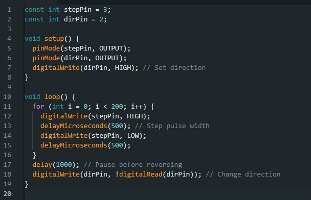
Figure 3. Sample program in the loop function for stepper motor pulse generation with a 500-microsecond step pulse width. Image used courtesy of the author
The alternative is using the AccelStepper library (which is one of many stepper libraries for the Arduini IDE), which offers flexibility in motor speed control, distance, and simultaneous control of multiple motors. With this library, you first need to initialize an instance of each motor, which can then be called to run continuously using a simple ‘run( )’ function that is reusable within the code.

Figure 4. Sample Arduino using AccelStepper library for multi-axis bidirectional stepper motor control for smooth acceleration and deceleration. Image used courtesy of the author
Programming and Control Logic: PLC
There are several methods of handling stepper motor control in the PLC. A previous stepper motor control project with the Mitsubishi FX Series PLC worked well for this project, as there were high levels of flexibility when it came to speed and direction. For this project, drive relative instruction (DRVI), which allows control by defining the number of pulses and the direction of movement of the motor, was used to implement relative motion logic.
DRVI increments the position of the motor rotation until a condition to stop the instruction is triggered. For instance, limit switches X002 and X003 can be used to stop the motor control instructions in the ladder logic below, ultimately stopping the motion of the stepper motors.
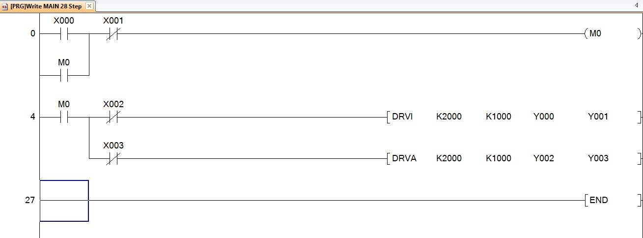
Figure 5. Sample ladder logic program driving two stepper motor axes: DRVI (drive incremental) and DRVA (drive absolute) instructions with limit switches X002 and X003 to halt motion, one for each axis. Image used courtesy of the author
DRVA instruction is used in cases where absolute positioning is needed. To further enhance flexibility in control, data registers are used in conjunction with a human-machine interface (HMI) to handle variable inputs like frequency and the number of pulses. To best manipulate these variables in Mitsubishi PLCs, the MOV instruction is used to transfer constants within a ladder, allowing flexibility in parameter settings. For instance, an HMI can have a number input interface that stores the keyed-in value to a data register such as D3 that can later be used in a control logic as represented below.
For more complex multi-axis control applications that need coordination and interpolation, a dedicated positioning module can be paired with the PLC. Despite advanced instructions like DRVI and DRVA having the ability to handle synchronized motions, they cannot easily generate complex motion profiles or smooth curved paths in multiple-axis control. These dedicated positioning modules offer high-level programming functions that simplify complex motion controls.
- Arduino: Flexible programming, but in a structured text format, perhaps not as easy for industrial technical professionals
- PLC: Ladder logic is more familiar, but less flexible for complex motion profiles without external module
Controller Selection for Automation Projects
Based on my practical assessment of the performance of the two controllers in the automation of the arc welding project, both controllers featured some share of strengths and weaknesses. Selecting the right controller for your automation project greatly depends on your specific needs in terms of performance and may require assessing aspects like EMI, vibrations, or even dust.
By carefully assessing factors like reliability, scalability, and maintainability, well-informed and context-driven decisions can be made by control engineers on the controller choices that best fit their automation projects.
Related Content


You didn’t mention an integration into the overall system. I can imagine, that with Arduino this would be practically impossible, whether PLC would offer wide range of communication connections without hassling with precise timing issues.
I used Arduino type boards with grbl software and off the shelf stepper controllers for a very cost effective door frame drilling setup. You can program it in standard G code which many people know and can handle curves, interpolation, etc.
By the way, I’m still here.