Robot-To-PLC Handshaking
Controlling an industrial robot can be done through the use of well-crafted signal handshakes. Follow along as we dive into several robot-to-PLC communication strategies.
In an automated environment, we use program instructions, oftentimes in ladder logic or structured text, to command robots and other equipment to do work. However, external devices like those robots and CNC machines do not have direct access to the internal programs of the control system or PLC. For this reason, we need to use handshake signals. But what signals do we need to send or receive from a robot, and does the brand of the robot matter?
Figure 1. Robots need to understand when it’s safe to start and stop operations. This is accomplished through handshaking with a control system. Image used courtesy of Unsplash
In the following article, I’ll outline some of the common methods for issuing commands to the robot and a few of the common signals that are required to initialize the robot task sequence.
Safety Signals
If you are using a standard industrial robot, you will need to supply the robot with some signal that initially informs the robot that the system is safe to power on. These signals typically consist of an ‘E-stop ok’ signal and a ‘guard door closed’ signal. These signals can be in the form of hard-wired signals from a safety PLC, safety relays, or over an Ethernet protocol such as CIP or ProfiSafe.
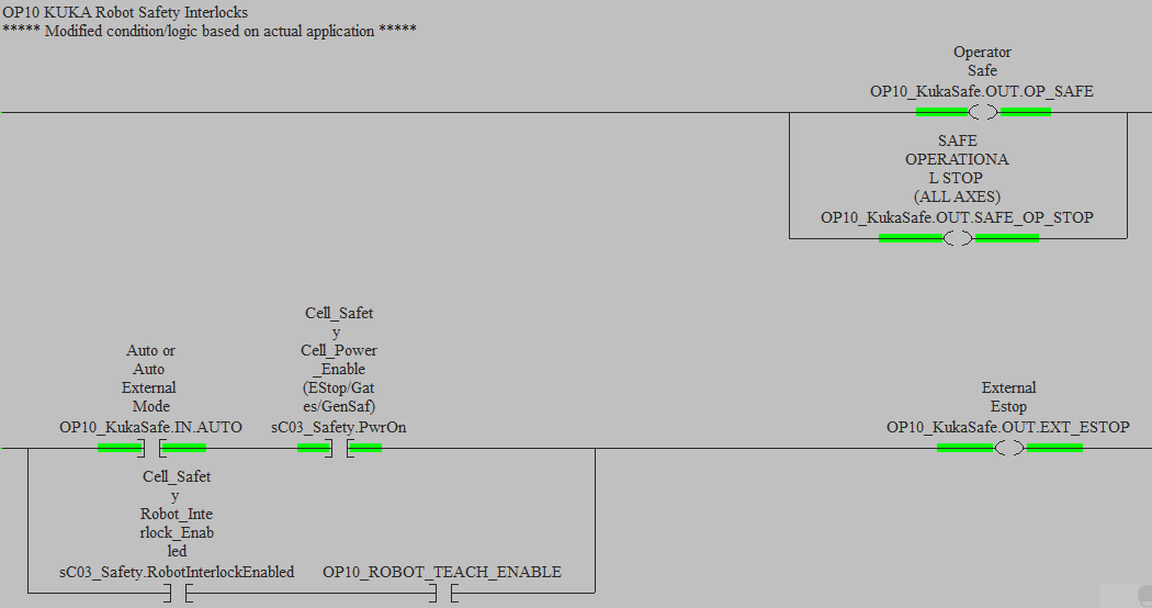
Figure 2. Safety interlock signals. Image used courtesy of the author
With some robots, such as the Epson SCARA robots, tying the ‘door closed’ signal to the robot E-stop signal is sufficient because it doesn’t have any different stop conditions. With ABB or FANUC, on the other hand, you can change the ‘stop mode’ category if somebody has either opened a door or pressed an E-stop.
With any safety system, always do an internal safety assessment to ensure your system is as safe as possible. In some regions, only one robot within a cell can be in teach mode at one time, so special logic needs to be added to the safety code.
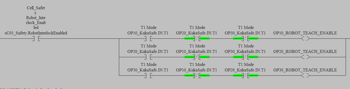
Figure 3. Example of having only one robot in teach mode. Image used courtesy of the author
Motors On And Off
Once the safety is satisfied, you will be able to initialize the servo power or turn the motors on. If your robot is using a Fieldbus communication technology, such as Ethernet/IP or PROFINET, you can simply set the ‘motors on’ bit within the mapped I/O. In some robots, such as Kawasaki, special parameter menus are used to map input signals to robot functions. Servo power is a common robot function that will need to be mapped to a specific input. ABB uses an EIO file to map system inputs to physical or Fieldbus inputs.
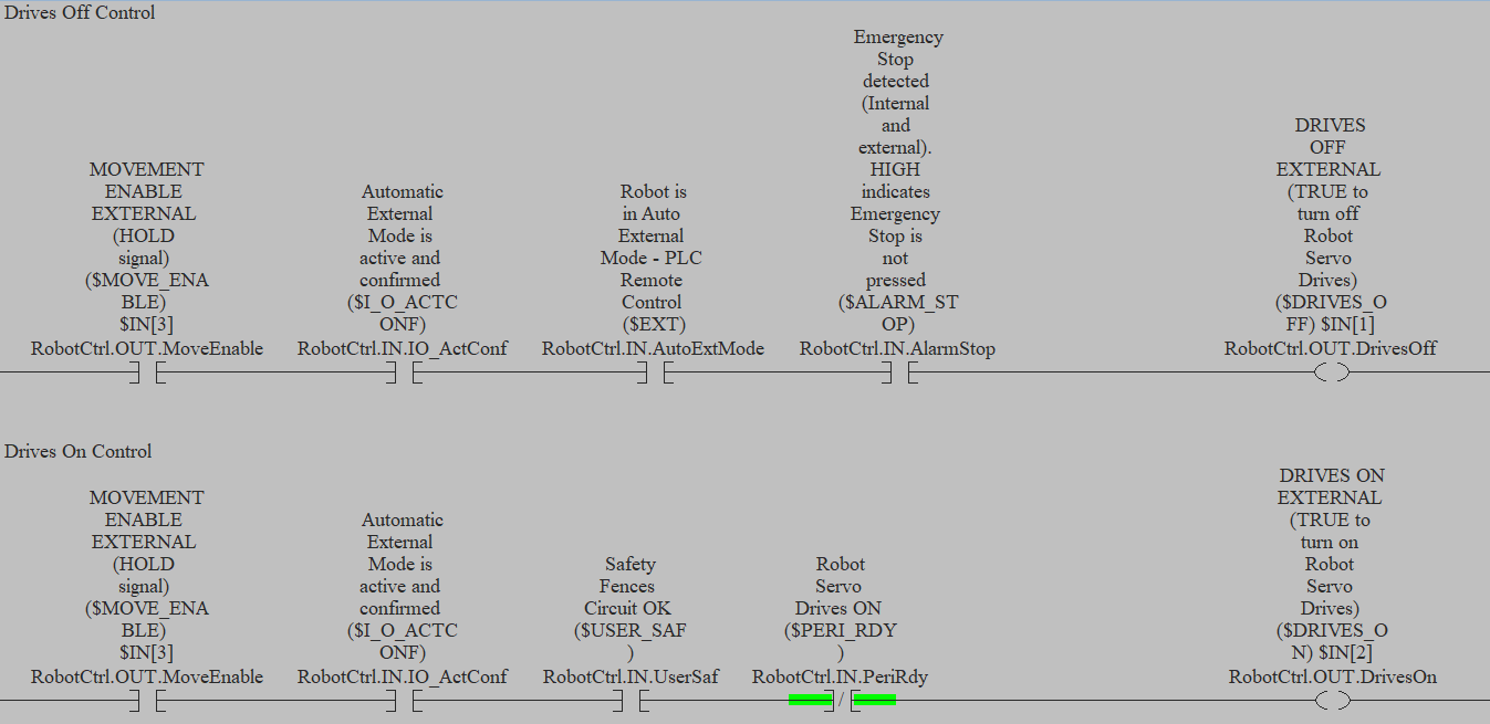
Figure 4. ‘Motors on’ and ‘motors off’ logic. Image used courtesy of the author
Conditions within your PLC program should be put in place, not only to initiate the servo power, fanucbut also to confirm the servo power actually came on.
When a fault occurs or if a condition occurs where you need to power down the servos, most robots have a drive-off command.

Figure 5. Coordinating robot motion requires connection to a central control system. Image used courtesy of Unsplash
Main Program And Program Numbers
This next part will depend on how you plan to issue commands to your robot. There are two methods that I will cover. One method involves using binary codes to call specific routines that are numbered instead of named. The other process sends command numbers to the robot via the Fieldbus, then a case statement is used in the program to call the different routines. Both methods work well and have their pros and cons.
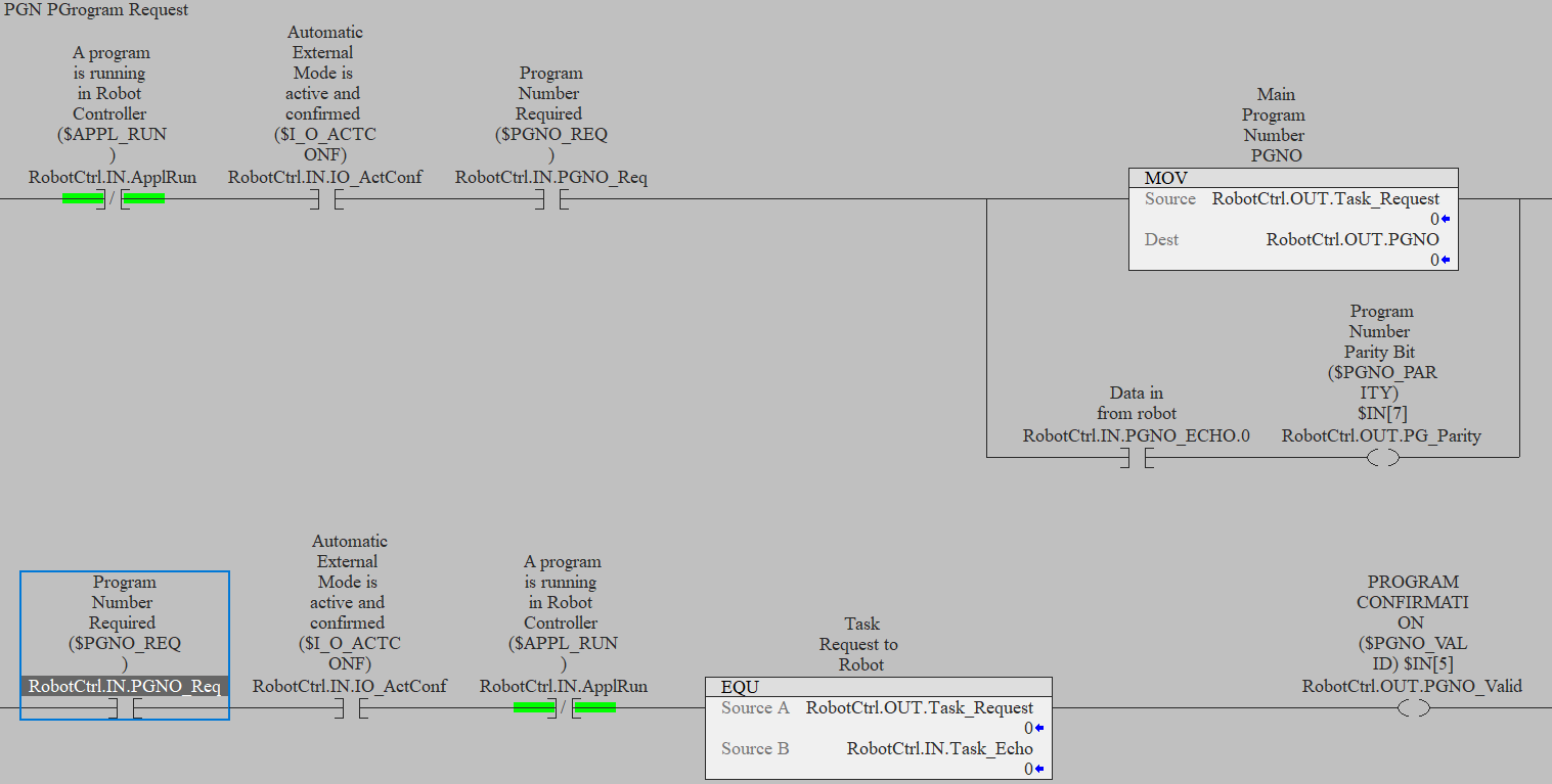
Figure 6. ‘Program number’ send and confirm. Image used courtesy of the author
Program number signals can be used to call different programs, with FANUC robots, these are called PNS signals, and KUKA robots call them PGNO numbers. These numbers represent a different task or program within the robot. Eight to sixteen consecutive inputs are mapped to the signals, and a similar set of output signals are also mapped. After the startup conditions are met, the PLC can set the signals and the robot will echo back the same signals on the outputs. The PLC program can then confirm the robot is returning the correct binary number and can issue the start command. Only the PLC logic is required to be programmed, the internal robot OS will take of receiving and echoing back the program number.
Command numbers sent to the robot can be used in a case statement to call different programs within the robot. This method requires the programmer to develop a continuous loop within the program where the robot will look for a new program number in a specific area of the input map and will send out the echo on the output registers. The PLC will again verify the robot is returning the correct numbers and will issue the start command.
A common hybrid method is used to help start the robot program in the main loop. A main program is given a program number, for example, PGNO 1, and when the robot is taken from teach to auto the PLC will command the robot to run PGNO 1. This starts the main loop and any initialization required. Once in the main loop, the PLC can then send command numbers as needed. When the commanded program is finished the program pointer will return to the main loop and look for another command number from the PLC.
Handshake Commands
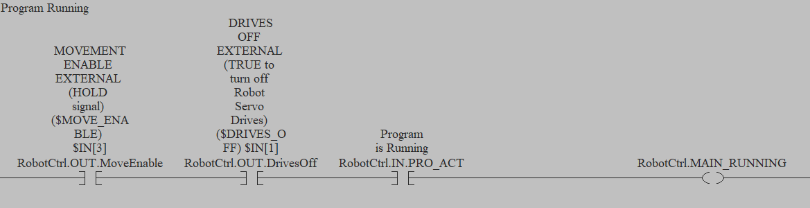
Figure 7. ‘Program running’ status. Image used courtesy of the author
Program Running
Whenever a program is started or when a command is sent to the robot, the PLC needs to know that the program is running. The PLC also needs to know that the robot has started from the main loop if you are using that control method. Robots such as Kawasaki have internal ‘program running’ status bits that can be mapped to Fieldbus outputs.
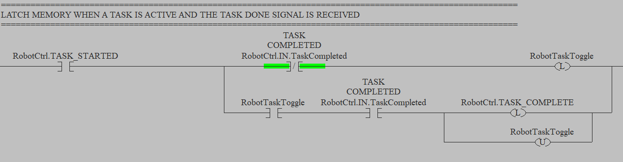
Figure 8. ‘Program complete’ status. Image used courtesy of the author
Program Complete
Some PLC logic might be driven off when a robot completes a specific task, we can also set faults to stop the equipment and alert operators if the robot doesn’t complete its task within a specific time frame. A task complete or program complete handshake can be programmed in at the end of all programs. This tells the PLC that the program has ended and the robot is ready for the next task. This ‘complete’ signal can also be set earlier in the program to advance the task call.

Figure 9. Developing proper communication systems can aid both the task and the operators. Image used courtesy of Unsplash
Handshake Logic
The above signals are just some common signals and methods to start and command a robot, and all of the methods and signals above use a common handshake method. Whenever you send a command or initiate a function on a robot there should be a status signal that ensures the function or command has occurred. Faults alert operators that something is not functioning the way it should be, and there should be a fault option available for every kind of signal you send to the robot. This method can be very helpful when troubleshooting why the robot isn’t moving or to prevent other equipment from causing a collision.


Thanks!
Very useful Information.