Facebook
 Google
 GitHub
 Linkedin
Virtual LAN for IT/OT Nodes in Industrial Control Systems
Virtual networks can connect or isolate various local control networks through configuration of a managed switch. Why would we use VLANs, and how can you segment a network switch to create a VLAN?
A virtual local area network, generally called VLAN, reflects a group of devices within a local area network (LAN) that can communicate with each other as if they are connected on the same physical cable or network device, even though they are in different LAN segments or devices. VLANs are based on logical connections instead of physical ones, therefore, they are very flexible and scalable network solutions.
Typical Control System Network Configuration
Modern industrial control systems are generally networked, and they communicate by using ethernet or fiber optic by monitoring process field data like flow, pressure, current, voltage, and switchyard breaker/isolator status. The high-performance servers communicate with field devices through process controllers which are connected via LAN networks using multiple industrial communication protocols like IEC 101/104 and Modbus between the master station and devices.
Local Area Network (LAN) Architecture
The normal control system configuration includes many control devices such as RTUs, PLC, relays, servers, applications such as SCADA application servers, archiving or UDW servers, and operator workstations and may be partitioned into the sites connected through LAN. The LAN is connected through routers/switches and is not owned by any single computer and node, all the computers are equal in relation to the LAN.

Figure 1. Switches are the primary distribution point for device-level networking. There are managed and unmanaged network switches. Image used courtesy of Adobe Stock
The control system's main functions include data acquisition, monitoring and control, data transmission, and data presentation at the HMI level. In the latest control systems for big power plants, all the equipment can be redundant at the network level, server level, and at site level.
Open system architecture-based control systems are rapidly adopted by the power generation, distribution, and transmission utility sector because it has the following major advantages
- Interconnection flexibility (LAN, WAN)
- Interoperability, the cooperation between programs for a true multi-vendor environment
- Scalability in terms of expanding hardware, software, and database
- Portability due to multiple hardware supply possibilities
The open system makes it possible to integrate other systems and third-party functions and therefore raises the requirement for a secure IT infrastructure for the control system. Advanced industrial control systems are being developed to fulfill the requirements of the North American Electric Reliability Corporation Critical Infrastructure Protection (NERC CIP) requirements.
Layer-2 and Layer-3 Network Switches
The first-generation control system was not designed to connect to other systems, however, the second-generation control systems were limited to single-site networks. The inception of the 3rd generation and 4th generation SCADA systems supports multiple redundant networks and implementation of IoT technology, including features like scalability, interoperability, and security. Their importance and network topology, which is based on the network switches, can not be underestimated.
Network switches are used to interconnect the plant bus and terminal bus so that nodes can communicate over the local area network. All field and control devices are connected with the plant bus, and the terminal bus is often dedicated to exchanges between the servers and clients. The new industrial control system network usually consists of servers, workstations, PLC, RTU, and IEDs connected with layer-2 or layer-3 network switches.
A network switch moves data packets from an input interface to one or more output interfaces. In comparison to a hub, a switch prevents networks/ports from being flooded and it eliminates collisions by allowing bidirectional (full duplex) traffic flow. Switches have a lower latency than routers and are designed to be installed in a specific network segment. In the OSI model switches are defined as layer 2 devices. Many high-end switches are called layer 3 switches
Layer-2 Switch
Layer-2 switches operate on the data link layer and are mostly found in local networks. These types of switches are fast because they operate on hardware-based switching fabric which only analyzes the MAC addresses. Therefore, the forwarding rate of this type of switch is relatively high.
Layer-3 Switch
Layer-3 switches implement the same functionality as the layer 2 switch but they can additionally analyze packets on layer-3 and route IP packets between different IP segments.
Use of VLAN Technology in ICS Network
VLANs network the operator’s HMI, application server, archiving server, data engineering server, front-end servers, RTUs & PLCs, and numerical relays all together, regardless of their physical connection. VLAN allows you to split a single switch into multiple virtual switches, improving traffic management and security. It also allows network traffic to be segmented with dedicated bandwidth allocation, used to offer the required QoS for the application.
Multiple virtual local area networks can be created where physical switch segmentation is not a possibility in large and complex control networks. Through real-world examples, we will look at how different VLANs can be created in the switch to connect multiple nodes.
Let's consider an example of how to integrate the VLAN into an ICS network using a Cisco 48-port fully managed ethernet switch. Device management, like the creation of VLANs and port configuration, can be done using webUI and command line interface (CLI) using telnet or SSH via PuTTY software. It is pertinent to state that before the inception of VLAN technology, the only way to isolate traffic was to use 2 different switches. Using VLAN, we can assign specific VLAN numbers to different ports on the same switch. To make the best use of infrastructure, extra services such as office communication or voice may run over the same network.
Multiple servers and operator workstations can be connected to designated local ports of the managed switch, with multiple ports being assigned different VLAN numbers. VLAN1 is the default VLAN and cannot be modified or deleted.
There are 2 types of ports in VLAN, one is called an access port and the second one is called a trunk port. Access ports are used to connect the host devices and these ports are the member of a single VLAN. Trunk ports are the ports that are used for communication between switches and can be assigned to more than one VLAN. The ports in this particular Cisco switch are, by default, access ports.
In the switch, two VLANs are created, named VLAN10 and VLAN20, as shown below in Figure 2.

Figure 2. VLAN topology for ICS
VLAN 10 - Virtual network for the application servers, active directory servers, and operator workstations having network address 10.101.10.5 with subnet mask 255.255.255.0
VLAN 20 - Virtual network for RTU having network address 10.101.20.5 with subnet mask 255.255.255.0
The command “sh interfaces status” will display detailed summary information of all ports on the switch, including many that were not illustrated in the simplified diagram of Figure 2 above.
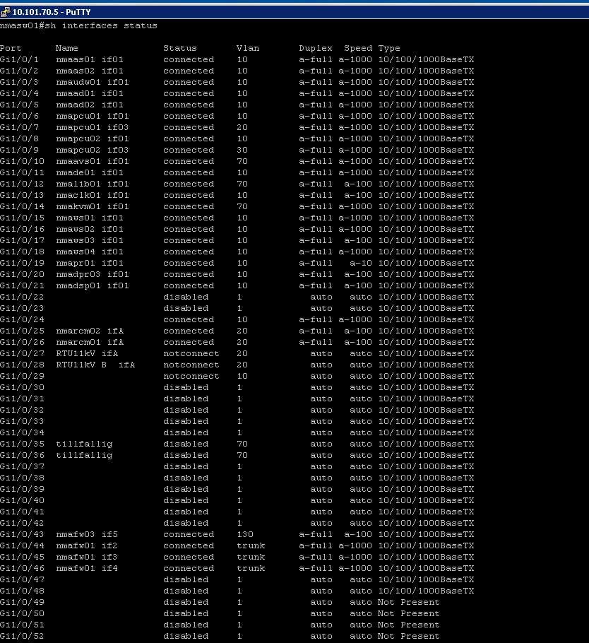
Figure 3. A detailed summary of information on all ports of the switch.
Example: Creating a VLAN and Assigning Switch Ports
First, create a VLAN and then add a port to the VLAN using the following command:
switch01(config)#vlan 10
This is optional, but we can enter a name for the VLAN i.e. 10.
switch01(config-vlan)# name vlan10
switch01(config)# end
Now some ports can be assigned to VLAN 10 using the following CLI commands by entering the configuration mode
switch01# config terminal
Enter the interface (port#1) to be added to the VLAN 10.
switch01 (config)# interface GigabitEthernet1/0/1
Define the VLAN mode for the port.
switch01(config-if)# switchport mode access
Finally, assign the port to a VLAN 10
switch01(config-if)# switchport access vlan 10
switch01(config)# end
Industrial Networking with VLANs
Industrial control systems always live at the edge of device-level networks, which prioritize reliability over speed and data rates, but also coinciding with remote networking and data storage, requiring amplified security and device management. VLANs can be a first step in segmenting a network to better manage those priorities and build a future-proofed, reliable communication system.
Featured image used courtesy of Adobe Stock
Related Content