Facebook
 Google
 GitHub
 Linkedin
What Can Go Wrong With Electrical Process Measurements?
Whether working with measurement tools or process controllers, it is important to recognize faulty display values and the best ways to fix them.
Electrical and electronic instrumentation is a critical part of the automation system, and the performance of attached equipment significantly depends on its satisfactory operation. Like other machine parts, instrumentation also malfunctions and affects the way an equipment is designed to perform.
For a successful maintenance strategy, it is necessary and beneficial to know the possible faults and defects, which helps to predict machine behavior and faults. It also increases the strength of maintenance personnel in keeping the equipment in a ready position.
Common Measurement Errors
Faulty measurement values are a pretty common occurrence, but having the skills to identify the root cause of the problem and having an understanding of how to fix it are not. The following are the most common causes of measurement errors.
Electrical Shorts: Damage to the Instrument
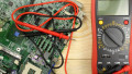
Electrical shorts are a common instrumentation problem in which the positive and negative terminals of a power supply (including batteries) are connected with no resistance, causing a short circuit condition.

Figure 1. Sudden sparking explosions are usually due to short circuits. Increased resistance from corrosion can also lead to fires but through the slower process of overheating. Image used courtesy of Adobe Stock
In the context of voltage measurement, a short will not result in failure. Many technicians directly measure the voltage at the supply terminals. However, when measuring resistance or current, it will likely result in a malfunction of the connected instrument, and in many cases, the device becomes dead and inoperable. Regardless, damaged insulation, exposing the conductor, is the most common cause of electrical shorts. To prevent electrical shorts from causing further damage, be sure to test resistance only when the circuit is powered off or disconnected. Be sure also to only measure current with a non-contact meter, or if you are certain that a series resistive load is securely connected.
Wire Disconnection: Random Values
Wire disconnection, as the condition suggests, is the discontinuation of wire carrying signal information such as 4–20 mA or 0–10 V in the instrumentation system. Also referred to as an open circuit condition, disconnection usually results from dust exposure, high temperatures, vibration, or shock. Disconnections can also occur when wires are woven together to form cable, rather than a single-wire solid metal conductor.

Figure 2. Wire disconnect is a common problem in measuring instruments and can occur due to dust, stress, high temperature, and using fragmented pieces of cable, instead of a single cable. Image used courtesy of Adobe Stock
When wiring disconnections occur, the values on the instrument display may appear either random or show the maximum data value. Random values can be generated by a nearby EMI source inducing voltage on an open wire. If EMI is not a factor, the most likely values to see are 0 volts if neither wire end is connected to an energized source, or maximum signal voltage if one wire is connected to an energized voltage source.
In process control instruments, the HMI display may exceed a user-defined threshold limit when the circuit is disconnected, and the display may default to an invalid reading, such as “### or ***” for example. This event may also trigger an alarm, indicating failure to read specific process variables.
Corrosion: Higher Resistance and Heat
Simply put, corrosion is the degradation of the metallic parts of electrical/electronic components. Corrosion can be caused by many things, including humidity, dust, and chemical agents—all common in most process and manufacturing industry environments.
Corrosion increases the resistance of a connection point and affects the electrical signal carried by the wire. Because, when designing an electrical/electronic system, conductors are precisely specified to not offer high controller resistance. High resistance can prevent the controller from receiving proper voltage, which can cause erratic readings. Corrosion also increases the temperature of the connection. The subsequent increase in terminal resistance, and decrease in current flow, can generate enough heat to melt insulation.

Figure 3. Corrosion is more common in older installations or humid environments. Image used courtesy of Adobe Stock
Selecting non-corrosive materials for terminals and similar components is a good start. Plating and anodizing terminals are another way to avoid corrosion. Regardless, designers and engineers need to address possible sources of corrosion and take measures to prevent it, well before the product is manufactured.
Improper Range Selection: Invalid Values
Improper range selection happens when using a manually-ranging meter with a sensor or transducer that does not correlate with each other. For every measuring instrument, a sensor having a specific resistance, current, or voltage is required for accurate variable measurement
If the meter and the signal’s ranges do not correlate, it will result in extreme readings on the meter. The reading on the display can not exceed the specific range limit, so the measured value may be displayed as “OL” or as the maximum possible value.
This problem often occurs during sensor or meter replacement. However, the problem can be addressed by selecting the sensor or meter after consulting with the respective manuals of machines and components.
Improper Scaling: Wrong Value
Many analog instruments correlate the incoming signal to a real-world quantity. These controllers often have selectable proportional scales. An example might be a temperature transducer where 1 mV equals 1 degree on one scale, while 10 mV equals 1 degree on a more sensitive scale. If the improper scale is selected, the real-world and displayed values will change at the same time, but will not be correct.
Thermocouple measurements, in particular, must always contain a linear scaling factor matching the metal junction type to the mV correction factor. If the wrong thermocouple type is selected, the actual and displayed values will also be incorrect.

Figure 4. Measurements are only as accurate as the connection wires. Loose or improper connections can lead to unstable readings. Image used courtesy of Adobe Stock
Improper Installation: Unstable Readings
Improper installation of a meter or instrument can take many forms.
- Leads are not securely and tightly connected (torqued) to terminals
- Reversed terminal connection of sensor
- Improper common (COM) ground connections
- Instruments/sensors and other electronic components not mounted securely inside an electrical panel
- Insufficient insulation, exposing the conductor and grounding to the enclosure’s inner wall
Improper installation causes erratic readings on the instrument and also risks the safety of electrical/electronic components.
To prevent improper installation, certainly follow installation specs, and pay special attention to the ground connection, using clean, high-quality wires with good insulation. It’s best to rely on experienced personnel to supervise installations. After that, it’s prudent to test the system before taking equipment for regular operation.
Configuration Changes: Erroneous Values
Configuration changes often come from unauthorized access and changes to instrument operating parameters. These parameters are set at the beginning of instrument installation and remain fixed under the same operating conditions.
The effect of configuration changes can include errors in reading physical variables or even errors in the output signals to control devices. The displayed or measured value no longer represents the actual legitimate value, resulting in inaccurate process decisions by the instrumentation system.
Unauthorized configuration changes are preventable by implementing password protection, limiting access to only one or two supervisors and only authorizing the operator to change operational parameters. It is also best practice to keep a backup copy of the existing parameters, which can be used in emergencies.
Error-Free Measurements
For developing an effective maintenance strategy, it is necessary to know the installed instrumentation and what problems they often face. The errors and solutions presented above are some of many that are useful for preventing a breakdown in a machine, or as a resource for beginners to troubleshoot and identify problematic electrical and electronic measurements.