 Facebook
 Google
 GitHub
 Linkedin
Digital Multimeter (DMM) Tips and Tricks
The digital multimeter (DMM) is quite possibly the most useful tool in the instrument technician’s collection. This one piece of test equipment, properly wielded, yields valuable insight into the status and operation of many electrical and electronic systems. Not only is a good-quality multimeter capable of precisely indicating electrical voltage, current, and resistance, but it is also useful for more advanced tests. The subject of this section is how to use a digital multimeter for some of these advanced tests.
For all these tests, I suggest the use of a top-quality field multimeter. I am personally a great fan of Fluke brand meters, having used this particular brand for nearly my whole professional career. The ability of these multimeters to accurately measure true RMS amplitude, discriminate between AC and DC signals, measure AC signals over a wide frequency range, and survive abuse both mechanical and electrical, is outstanding.
Recording unattended measurements
Many modern multimeters have a feature that records the highest and lowest measurements sensed during the duration of a test. On Fluke brand multimeters, this is called the Min/Max function. This feature is extremely useful when diagnosing intermittent problems, where the relevant voltages or currents indicating or causing the problem are not persistent, but rather come and go. Many times I have used this feature to monitor a signal with an intermittent “glitch,” while I attended to other tasks.
The most basic high-low capture function on a multimeter only tells you what the highest and lowest measured readings were during the test interval (and that only within the meter’s scan time – it is possible for a very brief transient signal to go undetected by the meter if its duration is less than the meter’s scan time). More advanced multimeters actually log the time when an event occurs, which is obviously a more useful feature. If your tool budget can support a digital multimeter with “logging” capability, spend the extra money and take the time to learn how this feature works!
Avoiding “phantom” voltage readings
My first “trick” is not a feature of a high-quality DMM so much as it is a solution to a common problem caused by the use of a high-quality DMM. Most digital multimeters exhibit very high input impedance in their voltage-measuring modes. This is commendable, as an ideal voltmeter should have infinite input impedance (so as to not “load” the voltage signal it measures). However, in industrial applications, this high input impedance may cause the meter to register the presence of voltage where none should rightfully appear.
Consider the case of testing for the absence of AC voltage on an isolated power conductor that happens to lie near other (energized) AC power conductors within a long run of conduit:
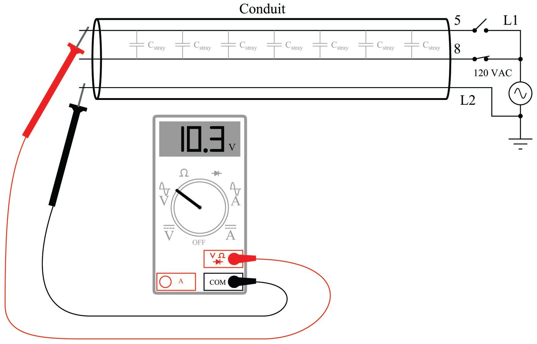
With the power switch feeding wire 5 in the open state, there should be no AC voltage measured between wire 5 and neutral (L2), yet the voltmeter registers slightly over 10 volts AC. This “phantom voltage” is due to capacitive coupling between wire 5 and wire 8 (still energized) throughout the length of their mutual paths within the conduit.
Such phantom voltages may be very misleading if the technician encounters them while troubleshooting a faulty electrical system. Phantom voltages give the impression of connection (or at least high-resistance connection) where no continuity actually exists. The example shown, where the phantom voltage is 10.3 volts compared to the source voltage value of 120 volts, is actually quite modest. With increased stray capacitance between the conductors (longer wire runs in close proximity, and/or more than one energized “neighboring” wire), phantom voltage magnitude begins to approach that of the source voltage.
The equivalent circuit is shown here, with the DMM modeled as a 10 M\(\Omega\) resistance:
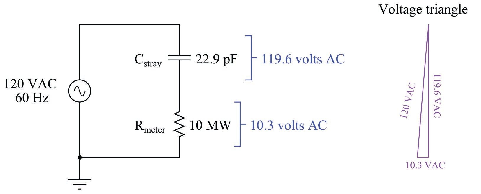
An analog voltmeter would never have registered 10.3 volts under the same conditions, due to its substantially lower input impedance. Thus, “phantom voltage” readings are a product of modern test equipment more than anything else.
The obvious solution to this problem is to use a different voltmeter – one with a much lesser input impedance. But what is a technician to do if their only voltmeter is a high-impedance DMM? Connect a modest resistance in parallel with the meter input terminals, of course! Fluke happens to market just this type of accessory, the SV225 “Stray Voltage Adapter” for the purpose of eliminating stray voltage readings on a high-impedance DMM:
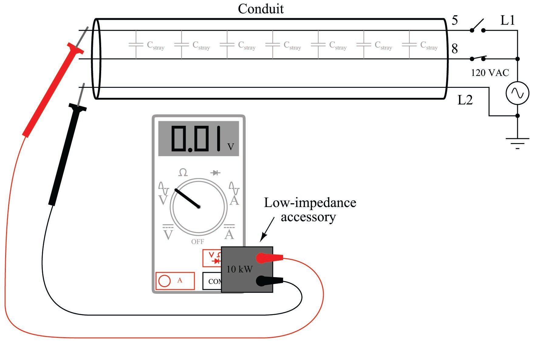
With the voltmeter’s input impedance artificially decreased by the application of this accessory, the capacitive coupling is insufficient to produce any substantial voltage dropped across the voltmeter’s input terminals, thus eliminating. The technician may now proceed to test for the presence of AC control signal (or power) voltages with confidence.
Non-contact AC voltage detection
While the last multimeter “trick” was the elimination of a parasitic effect, this trick is the exploitation of that same effect: “phantom voltage” readings obtained through capacitive coupling of a high-impedance voltmeter to a conductor energized with AC voltage (with respect to ground). You may use a high-impedance AC voltmeter to perform qualitative measurements of ground-referenced AC power voltage by setting the meter to the most sensitive AC range possible, grounding one test lead, and simply touching the other test lead to the insulation of the conductor under test. The presence of voltage (usually in the range of millivolts AC) upon close proximity to the energized conductor will indicate the energization of that conductor.
This trick is useful for determining whether or not particular AC power or control wires are energized in a location where the only access you have to those wires is their insulating sheaths. An example of where you might encounter this situation is where you have removed the cover from a conduit elbow or other fitting to gain access to a wire bundle, and you find those wires labeled for easy identification, but the wires do not terminate to any exposed metal terminals for you to contact with your multimeter’s probe tips. In this case, you may firmly connect one probe to the metal conduit fitting body, while individually touching the other probe tip to the desired conductors (one at a time), watching the meter’s indication in AC millivolts.
Several significant caveats limit the utility of this “trick:”
- The impossibility of quantitative measurement
- The potential for “false negative” readings (failure to detect a voltage that is present)
- The potential for “false positive” readings (detection of a “phantom voltage” from an adjacent conductor)
- The exclusive applicability to AC voltages of significant magnitude (\(\geq\) 100 VAC)
Being a qualitative test only, the millivoltage indication displayed by the high-impedance voltmeter tells you nothing about the actual magnitude of AC voltage between the conductor and ground. Although the meter’s input impedance is quite constant, the parasitic capacitance formed by the surface area of the test probe tip and the thickness (and dielectric constant) of the conductor insulation is quite variable. However, in conditions where the validity of the measurement may be established (e.g. cases where you can touch the probe tip to a conductor known to be energized in order to establish a “baseline” millivoltage signal), the technique is useful for quickly checking the energization status of conductors where ohmic (metal-to-metal) contact is impossible.
For the same reason of wildly variable parasitic capacitance, this technique should never be used to establish the de-energization of a conductor for safety purposes. The only time you should trust a voltmeter’s non-indication of line voltage is when that same meter is validated against a known source of similar voltage in close proximity, and when the test is performed with direct metal-to-metal (probe tip to wire) contact. A non-indicating voltmeter may indicate the absence of dangerous voltage, or it may indicate an insensitive meter.
Detecting AC power harmonics
The presence of harmonic voltages in an AC power system may cause many elusive problems. Power-quality instruments exist for the purpose of measuring harmonic content in a power system, but a surprisingly good qualitative check for harmonics may be performed using a multimeter with a frequency-measuring function.
Setting a multimeter to read AC voltage (or AC current, if that is the quantity of interest) and then activating the “frequency” measurement function should produce a measurement of exactly 60.0 Hz in a properly functioning power system (50.0 Hz in Europe and some other parts of the world). The only way the meter should ever read anything significantly different from the base frequency is if there is significant harmonic content in the circuit. For example, if you set your multimeter to read frequency of AC voltage, then obtained a measurement of 60 Hz that intermittently jumped up to some higher value (say 78 Hz) and then back down to 60 Hz, it would suggest your meter was detecting harmonic voltages of sufficient amplitude to make it difficult for your meter to “lock on” to the fundamental frequency.
It is very important to note that this is a crude test of power system harmonics, and that measurements of “solid” base frequency do not guarantee the absence of harmonics. Certainly, if your multimeter produces unstable readings when set to measure frequency, it suggests the presence of strong harmonics in the circuit. However, the absence of such instability does not necessarily mean the circuit is free of harmonics. In other words, a stable reading for frequency is inconclusive: the circuit might be harmonic-free, or the harmonics may be weak enough that your multimeter ignores them and only displays the fundamental circuit frequency.
Identifying noise in DC signal paths
An aggravating source of trouble in analog electronic circuits is the presence of AC “noise” voltage superimposed on DC signals. Such “noise” is immediately evident when the signal is displayed on an oscilloscope screen, but how many technicians carry a portable oscilloscope with them for troubleshooting?
A high-quality multimeter exhibiting good discrimination between AC and DC voltage measurement is very useful as a qualitative noise-detection instrument. Setting the multimeter to read AC voltage, and connecting it to an signal source where pure (unchanging) DC voltage is expected, should yield a reading of nearly zero millivolts. If noise is superimposed on this DC signal, it will reveal itself as an AC voltage, which your meter will display.
Not only is the AC voltage capability of a high-quality (discriminating) multimeter useful in detecting the presence of “noise” voltage superimposed on analog DC signals, it may also give clues as to the source of the noise. By activating the frequency-measuring function of the multimeter while measuring AC voltage (or AC millivoltage), you will be able to track the frequency of the noise to see its value and stability.
Once on a job I was diagnosing a problem in an analog power control system, where the control device was acting strangely. Suspecting that noise on the measurement signal line might be causing the problem, I set my Fluke multimeter to measure AC volts, and read a noise voltage of several tenths of a volt (superimposed on a DC signal a few volts in magnitude). This told me the noise was indeed a significant problem. Pressing the “Hz” button on my multimeter, I measured a noise frequency of 360 Hz, which happens to be the “ripple” frequency of a six-pulse (three-phase) AC-to-DC rectifier operating on a base frequency of 60 Hz. This told me where the likely source of the noise was, which led me to the physical location of the problem (a bad shield on a cable run near the rectified power output wiring).
Generating test voltages
Modern digital multimeters are fantastically capable measurement tools, but did you know they are also capable of generating simple test signals? Although this is not the design purpose of the resistance and diode-check functions of a multimeter, the meter does output a low DC voltage in each of these settings.
This is useful when qualitatively testing certain instruments such as electronic indicators, recorders, controllers, data acquisition modules, and alarm relays, all designed to input a DC voltage signal from a 250 ohm resistor conducting the 4-20 mA electronic transmitter signal. By setting a multimeter to either the resistance (\(\Omega\)) or diode check function and then connecting the test leads to the input terminals of the instrument, the instrument’s response may be noted.
Of course, this is a qualitative test only, since multimeters are not designed to output any precise amount of voltage in either the resistance or diode-check modes. However, for testing the basic response of a process indicator, recorder, controller, data acquisition channel, DCS input, or any other DC-signal-receiving devices, it is convenient and useful. In every multimeter I have ever tried this with, the diode-check function outputs more voltage than the resistance measurement function. This gives you two levels of “test signal” generation: a low level (resistance) and a high level (diode check). If you are interested in using your multimeter to generate test voltages, I recommend you take the time to connect your multimeter to a high-impedance voltmeter (such as another digital multimeter set to measure DC volts) and note just how much voltage your meter outputs in each mode. Knowing this will allow you to perform tests that are more quantitative than qualitative.
Using the meter as a temporary jumper
Often in the course of diagnosing problems in electrical and electronic systems, there is a need to temporarily connect two or more points in a circuit together to force a response. This is called “jumpering,” and the wires used to make these temporary connections are called jumper wires.
More than once I have found myself in a position where I needed to make a temporary “jumper” connection between two points in a circuit, but I did not have any wires with me to make that connection. In such cases, I learned that I could use my multimeter test leads while plugged into the current-sensing jacks of the meter. Most digital multimeters have a separate jack for the red test lead, internally connected to a low-resistance shunt leading to the common (black) test lead jack. With the red test lead plugged into this jack, the two test leads are effectively common to one another, and act as a single length of wire.
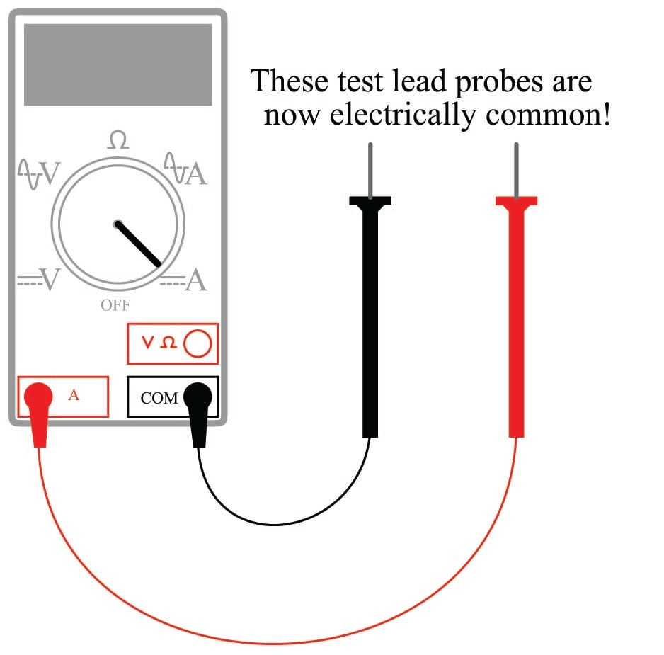
Touching the meter’s test leads to two points in a circuit will now “jumper” those two points together, any current flowing through the shunt resistance of the multimeter. If desired, the meter may be turned on to monitor how much current goes through the “jumper” if this is diagnostically relevant.
An additional benefit to using a multimeter in the current-measuring mode as a test jumper is that this setting is usually current-protected by a fuse inside the meter. Applying jumper wires to a live circuit may harbor some danger if significant potential and current-sourcing capability exist between those two points: the moment a jumper wire bridges those points, a dangerous current may develop within the wire. Using the multimeter in this manner gives you a fused jumper wire: an added degree of safety in your diagnostic procedure.
