 Facebook
 Google
 GitHub
 Linkedin
Flow Measurement from Differential Pressure
Since pressure changes along with fluid velocity, we should be able to correlate the two values
Pressure and flow rate are related, but not through a linear relationship. Instead, we must use a square-root relationship to convert the pressure change into a measurable flow.
In our first signal characterization example, we tackle the problem of measuring fluid flow through a pipe. To the layperson, this may seem to be a trivial problem. However there is no practical way to directly and continuously measure the flow rate of a fluid, especially when we cannot allow the fluid in question to become exposed to the atmosphere (e.g., when the liquid or gas in question is toxic, flammable, under high pressure, or any combination thereof).
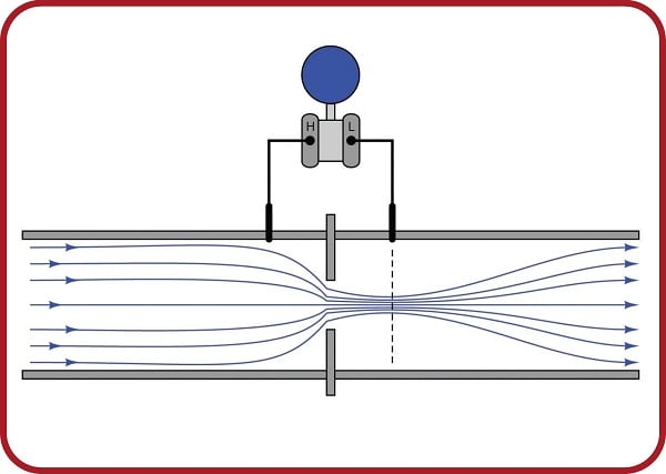
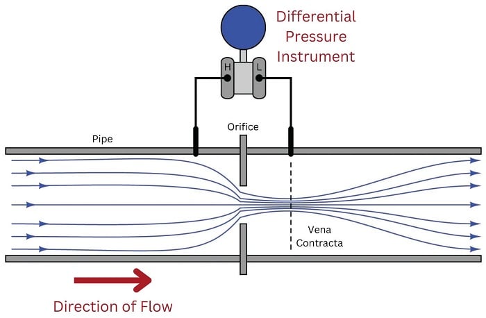
One standard way to measure the flow rate of a fluid through a pipe is to intentionally place a restriction in the path of the fluid, and measure the pressure drop across that restriction. The most common form of intentional restriction used for this purpose is a thin plate of metal with a hole precisely machined in the center, called an orifice plate.
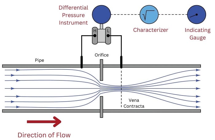
A side view of the orifice plate assembly and pressure-measuring instrument looks like this:
This approach should make intuitive sense: the faster the flow rate of the fluid, the greater the pressure difference developed across the orifice. The actual physics of this process has to do with the energy exchange between potential and kinetic forms, but that is incidental to this discussion. The mathematically interesting characteristic of this flow measurement technique is its nonlinearity. Pressure does not rise linearly with flow rate; rather, it increases with the square of the flow rate:
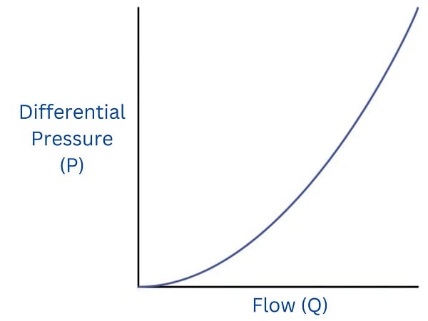
To write this as a proportionality, we relate flow rate (\(Q\)) to pressure (\(P\)) as follows (the constant \(k\) accounts for unit conversions and the geometries of the orifice plate and pipe):
\[P = k Q^2\]
This is a practical problem for us because our intent is to use pressure measurement (\(P\)) as an indirect (inferred) indication of flow rate (\(Q\)). If the two variables are not directly related to one another, we will not be able to regard one as being directly representative of the other. To make this problem more clear to see, imagine a pressure gauge connected across the restriction, with the face of the gauge labeled in percent:
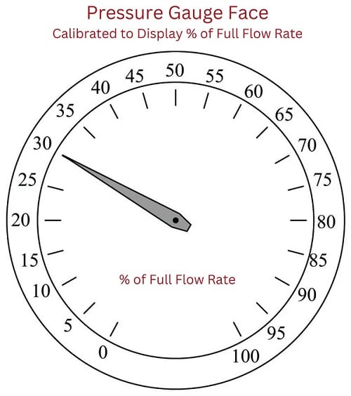
Consider a pressure gauge such as the one shown above, registering 20 percent on a linear scale at some amount of flow through the pipe. What will happen if the flow rate through that pipe suddenly doubles? An operator or technician looking at the gauge ought to see a new reading of 40 percent, if indeed the gauge is supposed to indicate flow rate. However, this will not happen. Since the pressure dropped across the orifice in the pipe increases with the square of flow rate, a doubling of flow rate will actually cause the pressure gauge reading to quadruple! In other words, it will go from reading 20% to reading 80%, which is definitely not an accurate indication of the flow increase.
A couple of simple solutions exist for addressing this problem. One is to re-label the pressure gauge with a “square root” scale. Examine this photograph of a 3-15 PSI receiver gauge:
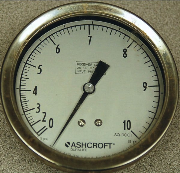
Now, a doubling of fluid flow rate still results in a quadrupling of needle motion, but due to the nonlinear (inner) scale on this gauge this needle motion translates into a simple doubling of indicated flow, which is precisely what we need for this to function as an accurate flow indicator.
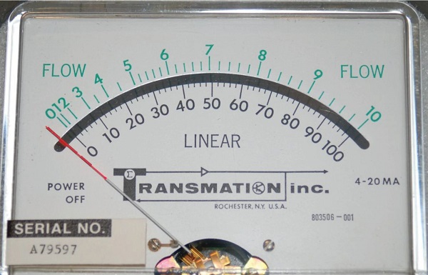
If the differential pressure instrument outputs a 4-20 mA analog electronic signal instead of a 3-15 PSI pneumatic signal, we may apply the same “nonlinear scale” treatment to any current meter and achieve the same result:
Another simple solution is to use a nonlinear manometer, with a curved viewing tube:
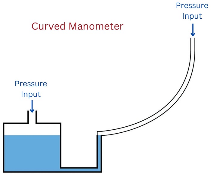
The scale positioned alongside the curved viewing tube will be linear, with equal spacings between division marks along its entire length. The vertical height of the liquid column translates pressure into varying degrees of movement along the axis of the tube by the tube’s curvature. Literally, any inverse function desired may be “encoded” into this manometer by fashioning the viewing tube into the desired (custom) shape without any need to print a nonlinear scale.
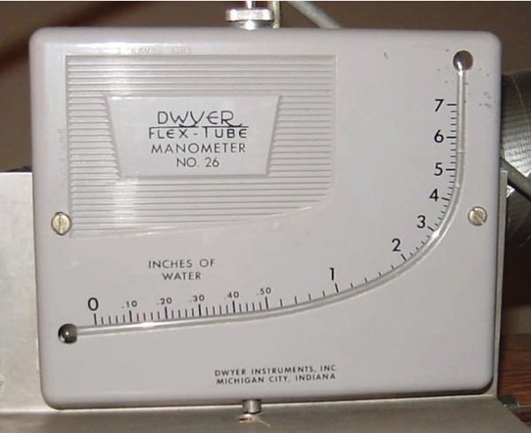
Shown here is a photograph of an actual curved-tube manometer. This particular specimen does not have a scale reading in units of flow, but it certainly could if it had the correct curve for a square-root characterization:
A more sophisticated solution to the “square root problem” is to use a computer to manipulate the signal coming from the differential pressure instrument so the characterized signal becomes a direct, linear representation of flow. In other words, the computer square-roots the pressure sensor’s signal in order that the final signal becomes a direct representation of fluid flow rate:
Both solutions achieve their goal by mathematically “un-doing” the nonlinear (square) function intrinsic to the physics of the orifice plate with a complementary (inverse) function. This intentional compounding of inverse functions is sometimes called linearization, because it has the overall effect of making the output of the instrument system a direct proportion of the input:
\[\hbox{Output} = k (\hbox{Input})\]
