 Facebook
 Google
 GitHub
 Linkedin
Basics of Electrical Current

How do we measure the motion of electrons in a circuit?
As with all branches of physics, kinetic energy and work in electrical circuits involves motion. Electron movement in a circuit drives the accomplishment of work for all electrical machines. Current is the measure of the rate at which electrons flow through the wires.
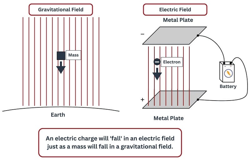
Current is the name we give to the motion of electric charges from a point of high potential to a point of low potential. All we need to form an electric current is a source of potential (voltage) and some electric charges that are free to move between the poles of that potential. For instance, if we connected a battery to two metal plates, we would create an electric field between those plates, analogous to a gravitational field except it only acts on electrically charged objects, while gravity acts on anything with mass. A free charge placed between those plates would “fall” toward one of the plates just as a mass would fall toward a larger mass:
Motion of Electrons in Metals
Some solid substances, most notably metals, have very mobile electrons. That is, the outer (valence) electrons are very easily dislodged from the parent atoms to drift to and fro throughout the material. In fact, the electrons within metals are so free that physicists sometimes refer to the structure of a metal as atomic nuclei “floating in a sea of electrons”. The electrons are almost fluid in their mobility throughout a solid metal object, and this property of metals may be exploited to form definite pathways for electric currents. This is why electrical wires are made of metal such as copper or aluminum: substances with a high degree of electron mobility. Any substance whose electrons are mobile is called an electrical conductor, while any substance lacking mobile electrons is called an electrical insulator.
Electrons Move in an Electrical Circuit
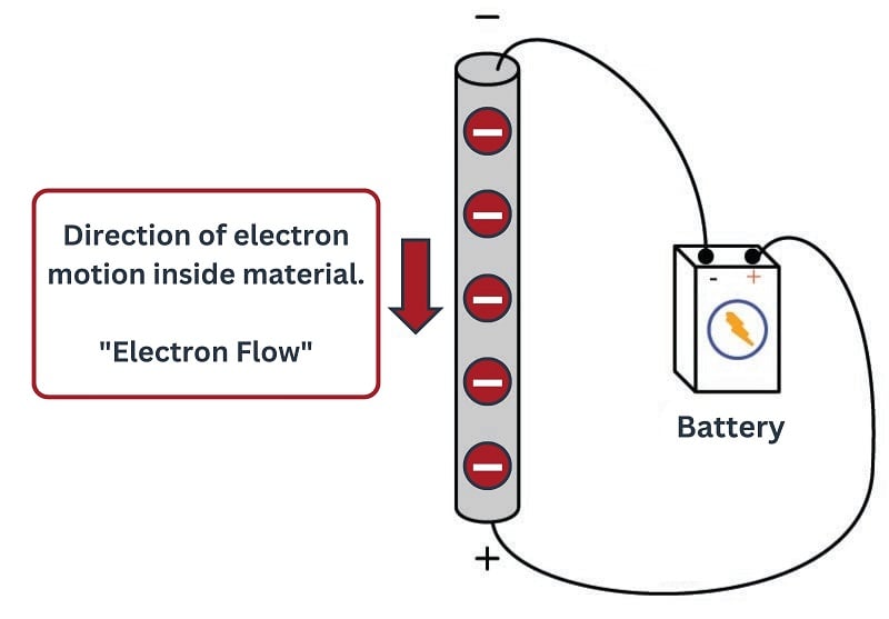
If the poles of a voltage source are joined by a conductor, the free electrons within that conductor will drift toward the positive pole (electrons having a negative charge, opposite charges attracting one another). For each electron reaching the positive pole, an electron exits the negative pole of the source to replenish the total number of electrons in the flow:
Current Means Consistent Direction of Electron Flow
If the source of this voltage is continually replenished by chemical energy, mechanical energy, or some other form of energy, the free electrons will continually loop around this circular path. We call this unbroken path an electric circuit. The drifting motion of electrons in a circuit has the same average rate of flow (current) at all points in that circuit, because there is only one pathway for the current. You may think of this like liquid flowing through a circular loop of pipe: since there is only one pathway for the liquid to flow, the rate of flow at all points in that pathway must be the same.
We typically measure the amount of current in a circuit by the unit of Amperes, or Amps for short (named in honor of the French physicist André Ampère, and symbolize it in formulae using the variable \(I\). One ampere of current is equal to one coulomb of electric charge (\(6.24 \times 10^{18}\) electrons) moving past a point in a circuit for every second of time.
Like masses falling toward a source of gravity, these electrons continually “fall” toward the positive pole of a voltage source. After arriving at that source, the energy imparted by that source “lifts” the electrons to a higher potential state where they once again “fall down” to the positive pole through the circuit.
Like rising and falling masses in a gravitational field, these electrons act as carriers of energy within the electric field of the circuit. This is very useful, as we can use them to convey energy from one place to another, using metal wires as conduits for this energy. This is the basic idea behind electric power systems: a source of power (a generator) is turned by some mechanical engine (windmill, water turbine, steam engine, etc.), creating an electric potential. This potential is then used to motivate free electrons inside the metal wires to drift in a common direction. The electron drift is conveyed in a circuit through long wires, where they can do useful work at a load device such as an electric motor, light bulb, or heater.

Given the proper metal alloys, the friction that electrons experience within the metal wires may be made very small, allowing nearly all the energy to be expended at the load (motor), with very little wasted along the path (wires). This makes electricity the most efficient means of energy transport known.
Amps (A) and Milliamps (mA)
The electric currents common in electric power lines may range from hundreds to thousands of amperes. The currents conveyed through power receptacles in your home typically are no greater than 20 amperes. The currents in the small battery-powered circuits you will build are even less: fractions of an ampere. For this reason, we commonly use the metric prefix milli (one one-thousandth) to express these small currents. For instance, 10 milliamperes is 0.010 amperes, and 500 milliamperes is one-half of an ampere.
Conventional Current vs Electron Flow
When Benjamin Franklin proposed his single-fluid theory of electricity, he defined “positive” and “negative” as the surplus and deficiency of electric charge, respectively. These labels were largely arbitrary, as Mr. Franklin had no means of identifying the actual nature of electric charge carriers with the primitive test equipment and laboratory techniques of his day.
Electron Current (Electron Flow)
As (bad) luck would have it, Franklin’s hypothesis of positive referring to the surplus of electrons was precisely the opposite of the truth for metallic conductors, where negatively-charged electrons are the dominant charge carrier.
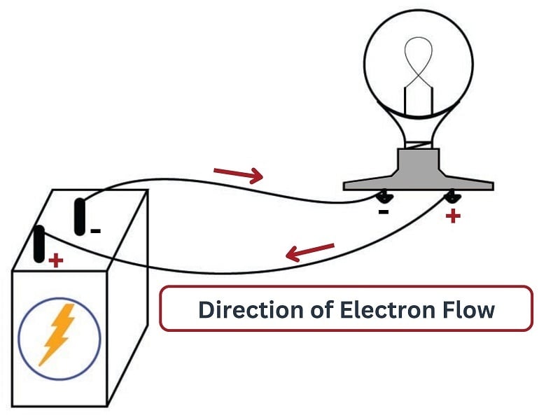
This means that in an electric circuit consisting of a battery and a light bulb, electrons slowly move from the negative side of the battery, through the metal wires, through the light bulb, and on to the positive side of the battery as such:
Conventional Current (Conventional Flow)
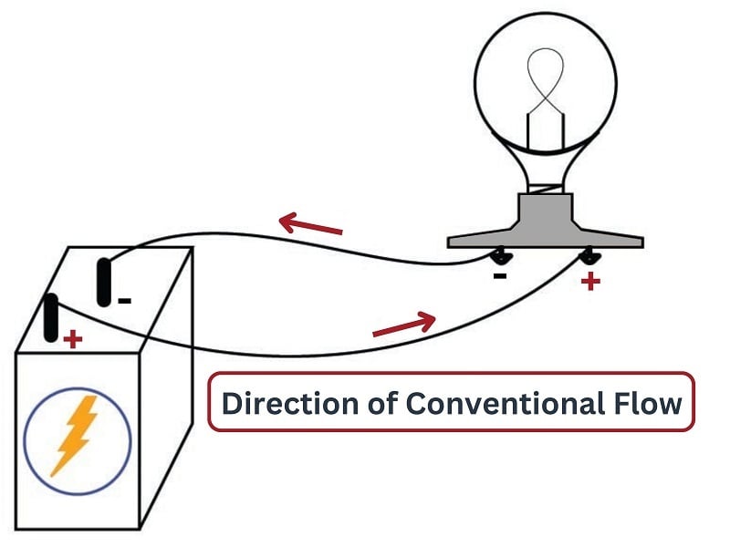
Unfortunately, scientists and engineers had grown accustomed to Franklin’s false hypothesis long before the true nature of electric current in metallic conductors was discovered. Their preferred notation was to show electric current flowing from the positive pole of a source, through the load, returning to the negative pole of the source:
This relationship between voltage polarity marks and conventional flow current tends to make more intuitive sense than electron flow notation, because it is reminiscent of fluid pressure and flow direction:

If we take the “+” sign to represent more pressure and the “\(-\)” sign to represent less pressure, it makes perfect sense that fluid should move from the high-pressure (discharge) port of the pump through the hydraulic “circuit” and back to the low-pressure (suction) port of the pump. It also makes perfect sense that the upstream side of the valve (a fluid restriction) will have a greater pressure than the downstream side of the valve. In other words, conventional flow notation best honors Mr. Franklin’s original intent of modeling current as though it were a fluid, even though he was later proven to be mistaken in the case of metallic conductors where electrons are the dominant charge carrier.
This convention was so well-established in the electrical engineering realm that it held sway despite the discovery of electrons. Engineers, who create the symbols used to represent the electronic devices they invent, consistently choose to draw arrows in the direction of conventional flow rather than electron flow. In each of the following symbols, the arrowheads point in the direction that positive charge carriers would move (opposite the direction that electrons actually move):

This stands in contrast to electronics technicians, who historically have been taught using electron flow notation. I remember sitting in a technical school classroom being told by my teacher to always imagine the electrons moving against the arrows of the devices, and wondering why it mattered.
It is truly a sad situation when the members of two branches within the same field do not agree on something as fundamental as the convention used to denote flow in diagrams. It is even worse when people within the field argue over which convention is best. So long as one is consistent with their convention and with their thinking, it does not matter! Many fine technologists may be found on either side of this “fence,” and some are adept enough to switch between both without getting confused.
The personal preference of many professionals is conventional flow notation. The only objective arguments I have in favor of this preference are as follows:
- Conventional flow notation is a closer analogue to fluid flow in pneumatic, hydraulic, and process flow systems. Since instrument technicians need to understand the relationships between pressure and flow in fluid systems as well as electrical circuits, using conventional flow notation for electrical circuits helps to reinforce these analogous concepts.
- Conventional flow notation is the standard for modern manufacturers’ documentation (reference manuals, troubleshooting guides, datasheets, etc.).
- Conventional flow notation is consistent with the “right-hand rule” for vector cross products (which are essential for understanding electromagnetics at advanced academic levels). The so-called “left-hand rule” taught to students learning electron flow notation is mathematically wrong, and must be un-learned if the student ever progresses to the engineering level in his or her studies.
- Conventional flow notation matches all device arrows; no need to “go against the arrow” when tracing current in a schematic diagram.
- Conventional flow notation makes sense of the descriptive terms sourcing and sinking.
“Source” and “Sink”
This last point merits further investigation. The terms “sourcing” and “sinking” are often used in the study of digital electronics to describe the direction of current in a switching circuit. A circuit that “sources” current to a load is one where the direction of conventional flow points outward from the sourcing circuit to the load device. These terms are also used to characterize the DC input and output modules of certain industrial control equipment such as programmable logic controllers (PLCs), and so any technologist working with such equipment will need to properly identify and connect these module types based on the directions of electric current for which they are designed.
For example, here are two schematic diagrams showing two different kinds of electronic proximity switch. The first switch sinks current in from the LED through its output terminal, through its transistor, and down to ground. The second switch sources current from the positive supply terminal through its transistor and out to the LED through its output terminal (note the direction of the arrow near the output (black wire) screw terminal in each circuit):
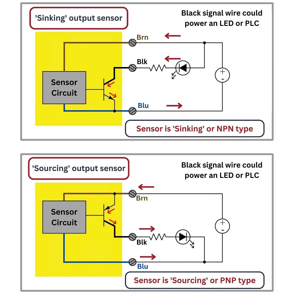
These terms simply make no sense when viewed from the perspective of electron flow notation. If you were to actually trace the directions of the electrons, you would find that a device “sourcing” current has electrons flowing into its connection terminal, while a device “sinking” current sends electrons out to another device where they travel (up) to a point of more positive potential.
In fact, the association between conventional flow notation and sourcing/sinking descriptions is so firm that I have yet to see a professionally published textbook on digital circuits that uses electron flow. This is true even for textbooks written for technicians and not engineers!
Choosing Flow Notation
Once again, though, it should be understood that either convention of current notation is adequate for circuit analysis. I dearly wish this horrible state of affairs would come to an end, but the plain fact is it will not. Electron flow notation may have the advantage of greater correspondence to the actual state of affairs (in the vast majority of circuits), but conventional flow has the weight of over a hundred years of precedent, cultural inertia, and convenience. No matter which way you choose to think, at some point you will be faced with the opposing view.
Choose the notation you like best, and may you live long and prosper.
REVIEW:
-
Electrical current is the consistent rate of motion of electrons freely moving through a conductive material
-
Voltage sources drive consistent electron movement, so all circuits must have voltage sources
-
Electron flow direction is the actual, realistic direction of electrons from negative (-) to positive (+).
-
Conventional current direction is notated as electron motion from positive (+) to negative (-).
-
Conventional flow is opposed to how electrons truly move, but symbolic consistency and document publications have made it the preferred notation for many engineering trades.

Thank you for the explanation. It is very insightful.
Thanks its really great well done