 Facebook
 Google
 GitHub
 Linkedin
Electrical Sources and Electronic Load
The two most fundamental parts of a circuit are the source and the load
The source generates power by converting it from a chemical or mechanical energy form into electricity, while the load consumes it by converting it back into motion, light, heat, or sound. The rest of the circuit simply formats the electricity to travel properly to the load.
By definition, a source is a device delivering energy into a system, while a load is a device extracting energy from a system. Examples of typical electrical sources include generators, photovoltaic cells, thermopiles, and primary-cell batteries. These devices create electrical voltage, which in turn motivates electrical current to flow in a circuit. Examples of typical electrical loads include resistors, lamps, and electric motors. These devices resist the flow of electrical current through them, creating a voltage drop as a result.
In a working circuit, electrical sources and loads may be easily distinguished by comparison of their current directions and voltage polarities. An electrical source always manifests a voltage polarity in a direction aiding the direction of charge flow; i.e. a source is “pushing” the current along. An electrical load always manifests a voltage polarity in a direction opposing the direction of charge flow; i.e. a load “resists” the current.
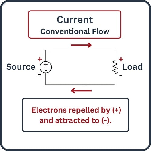
The way in which we designate the direction of current (charge flow) becomes very important here. Since there are two commonly accepted notations – electron flow and “conventional” flow, exactly opposite of each other – it is easy to become confused.
Electronic Source and Electronic Load
First we see a diagram showing a source and a load, using electron flow notation. Electrons, being negatively charged particles, are repelled by the negative (\(-\)) poles of both source and load, and attracted to the positive (+) poles of both source and load. The difference between source and load is that the source device motivates the flow of electrons while the load device resists the flow of electrons:
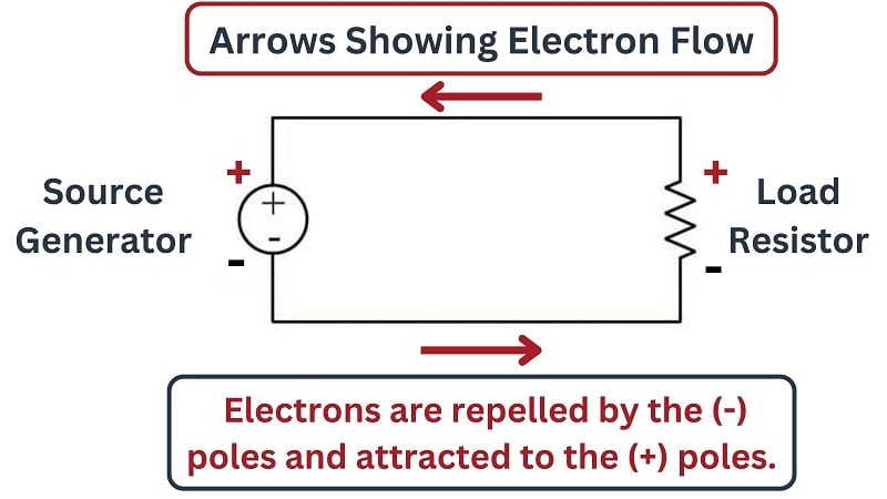
In the case of the source (battery), the polarity of the voltage works for the direction of charge motion. In the case of the load (resistor), the polarity of the voltage drop works against the direction of charge motion.
Next we see a diagram showing the same source and load, this time using “conventional” flow notation to designate the direction of current. Here we must imagine positively-charged carriers moving through the wires instead of electrons. These positive charge carriers are repelled by any positive (+) pole and attracted to any negative (\(-\)) pole. Viewed in this light, we see the exact same principle at work: the source device is seen to motivate the flow of these positive charge carriers while the load device resists the flow:
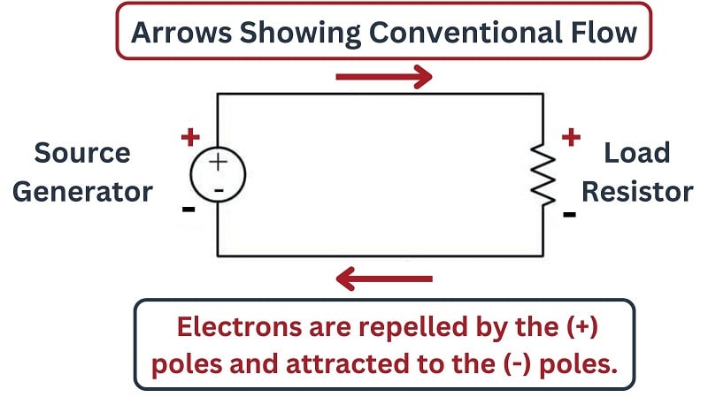
Despite using a different notation for charge motion, the concept of source and load remains the same. In the case of the source (battery), the polarity of the voltage works for the direction of charge motion. In the case of the load (resistor), the polarity of the voltage drop works against the direction of charge motion.
Voltage Polarity Notation
An alternative notation for voltage (other than using “+” and “\(-\)” symbols) that many students find particularly illustrative is the use of curved arrows, where the tip of the curved arrow is the positive pole and the tail of the curved arrow is the negative pole. This notation is intended to be used when the direction of current (using “straight” or “angular” arrows) is shown using conventional flow notation:
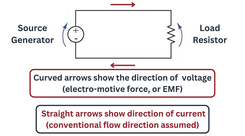
Using arrows to represent voltage polarity in addition to using arrows to represent current direction is highly intuitive. It shows which way each component in the DC circuit is “pushing” in relation to the flow of charge carriers.
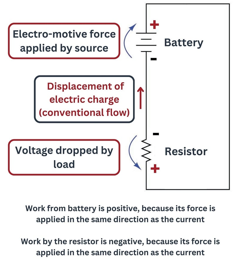
Electrical Source Generator
Note how the source’s voltage arrow points in the same direction as the current: this means the source is motivating the current, causing charge carriers to flow in this circuit.
Electrical Load Resistor
Note how the resistor’s voltage arrow points opposite to the direction of current: this means the resistor is opposing the current, in a sense “fighting against” the flow of charge carriers. This comparison of voltage-arrow versus current-arrow direction makes the distinction between sources and loads rather obvious: sources push in the direction of current while loads push against the direction of current.
I personally lament the obscurity of this “curved-arrow” notation for voltage, as it greatly aids comprehension of this critically important distinction between sources and loads. When the voltage and current arrows point in the same direction, it means the component in question is motivating charge carriers along and therefore imparts energy to the circuit. When voltage and current arrows point in opposite directions, it means the component in question opposes charge carrier motion and therefore acts to extract energy from the circuit.
Work and Force
This directly relates to the fundamental physics concept of work, specifically in relation to the mathematical sign of work being a function of the relative angle between force and displacement. When a force acts in the same direction as motion, the work done is positive; when a force acts in the opposite direction as motion, the work done is negative:
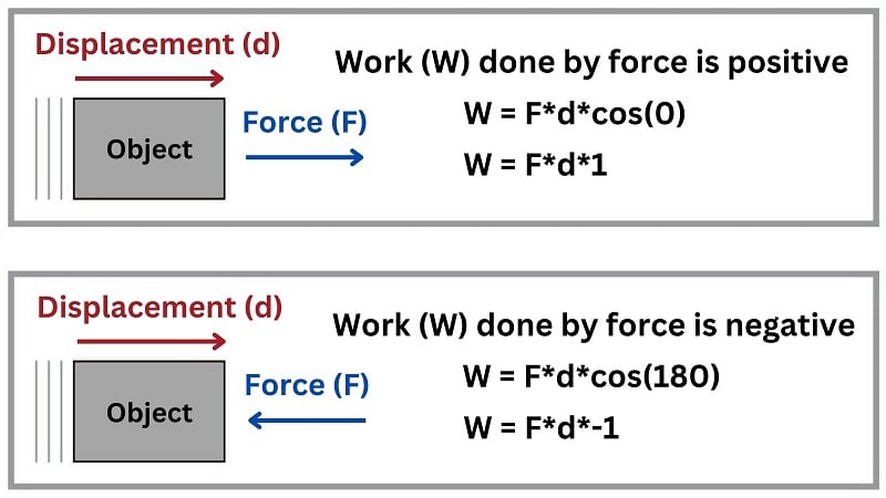
Positive work represents an infusion of energy into a system (source), while negative work represents an extraction of energy from that system (load).
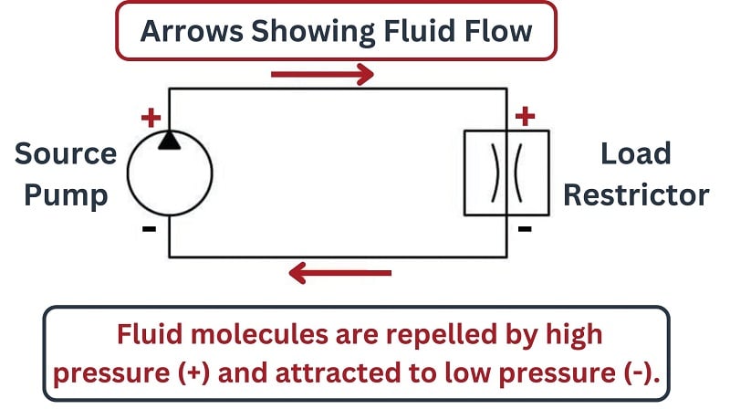
Hydraulic Analogy
Power Source and Power load
If we examine a hydraulic system, where a pump pushes fluid around a pipe loop and an orifice (called a “restrictor”) restricts the flow of this fluid, we see this same concept in action: the pump’s pressures at its discharge and suction ports work for the direction of fluid flow, while the pressures at the upstream and downstream ports of the restrictor work against the direction of fluid flow. The pump acts as a power source in this hydraulic “circuit” (infusing energy into the system) while the restrictor acts as a power load (extracting energy from the system):
We may even see this concept revealed in a simple mechanical system where work is being done. Examine the case of a crane lifting a heavy weight into the air, shown below. As the crane lifts the weight upward, the crane’s upward force on the weight is clearly working for the direction of motion, while the weight’s downward force against the crane is clearly working against the direction of motion:
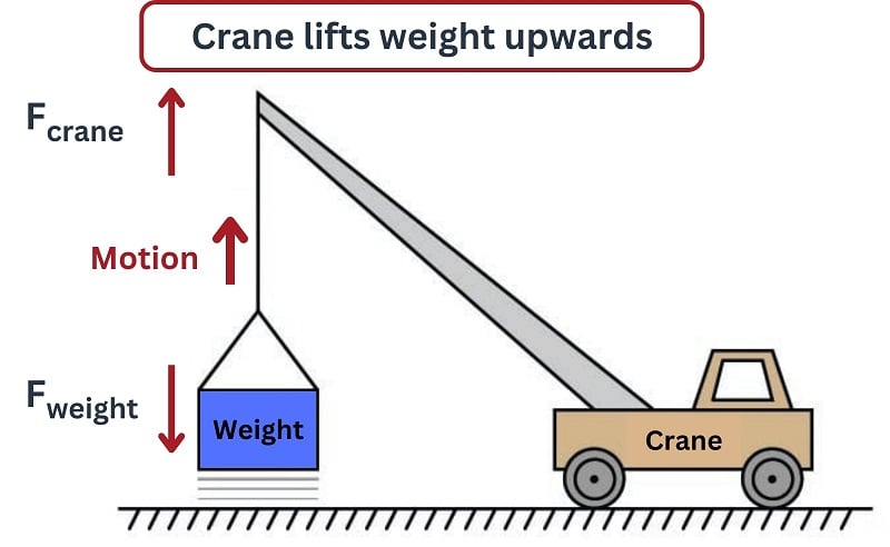
Thus, the crane is doing positive work (acting as a source, infusing potential energy into the weight) while the weight is doing negative work (acting as a load, absorbing potential energy from the crane). A mathematically rigorous way to demonstrate this is to calculate the work done by each using the formula \(W = \vec{F} \cdot \vec{x}\) or \(W = F x \cos \theta\). Since the crane’s force and motion vectors both point in the same direction, \(\theta = 0\) and work is a positive quantity \(Fx\). The weight’s force vector, however, points 180\(^{o}\) away from the motion vector, and so its work calculation is \(Fx \cos (180^o)\) or \(-Fx\).
Devices With Source and Load Properties
Capacitor and Inductor Energy Storage
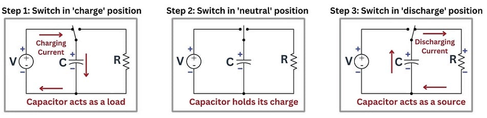
Some electric components have the ability to act as sources and loads at different times. Both capacitors and inductors have the ability to temporarily contribute to and extract energy from electrical circuits, both having the ability to act as energy storage devices. One of the key concepts necessary to grasp the energy-storing abilities of capacitors and inductors is being able to recognize sources and loads at a glance based on the relationship between voltage polarity and charge motion. A set of three schematic diagrams shows how a capacitor is able to play the role of either source or load depending on the rest of the components i nthe circuit:
Rechargeable Batteries
Rechargeable batteries (called “secondary-cell” batteries as opposed to “primary-cell” batteries which cannot be recharged) may also behave as either sources or loads depending on external conditions. If a secondary-cell battery is connected to a resistor, the battery will discharge its energy (i.e. act as a source) while the resistor will dissipate that energy (i.e. act as a load). If a depleted secondary-cell battery is connected to an electrical generator of greater voltage, the generator will source energy to the battery while the re-charging battery will load down the generator (i.e. conventional flow entering the battery’s positive terminal and exiting the negative terminal).
Analog 4-20 mA Signal Circuits
Another practical benefit of clearly comprehending the distinction between electrical sources and electrical loads is being able to understand and troubleshoot 4-20 mA signal “loop” circuits used extensively in industrial instrumentation, especially circuits containing 2-wire (“loop-powered”) process transmitters. A “2-wire transmitter” is a device designed to regulate the amount of electrical current through it to a value determined by some physical variable such as a sensed pressure, temperature, or flow rate.
The purpose of such a device is to represent that physical measurement in the form of an electric current that may be carried far distances through wires. What makes this device so troublesome for people to understand is that despite its function to set the value of current in the circuit, it is actually an electrical load and not an electrical source as one might assume. That is, a 2-wire transmitter relies wholly on some other source of electrical power in the circuit to function, although the transmitter solely defines how much current will flow in the circuit by virtue of its function as a regulator. For more information on this subject, refer to the section about analog signals, and take a look at the numerous articles containing theory and application of loop circuits.
Textbook:
Technical Articles:
- Why is 4-20 mA Current Used for Industrial Analog Sensors?
- Loop-powered (Two-wire) Transmitters for Analog Sensors
- Advanced Scaling Techniques for PLC Analog Quantities
- How to Use Analog to Digital Converters in a Control System
REVIEW:
-
Both source and load are essential circuit components for the conversion of energy into work accomplished.
-
Voltage polarity follows both electron flow and conventional current directions.
-
If a force is moved a certain distance (as is the goal in a machine), work is done, and power is used.
-
Some devices, including inductors, capacitors, and rechargeable batteries, can act as both sources or loads depending on how the circuit is configured.
