Facebook
 Google
 GitHub
 Linkedin
Loop-powered (Two-wire) Transmitters for Analog Sensors
In this introduction to loop-powered transmitters, also known as two-wire transmitters, we discuss operation, applications, and options for signal isolation, displays, digital data transmission, and mounting.
In process control systems, measurement signals are commonly converted to analog elevated-zero current: 4 to 20 milliamperes (4-20 mA). The signal is 4 mA at the low end of the range (0 percent) and 20 mA at full scale (100 percent).
Unless you have been working in industrial settings, most electronics systems you have seen transmit voltage signals with a 0 to some full-scale range. For example, 0 to 5 V.
Why 4-20mA Current Signalling?
So, you may wonder, “Why use current for signal transmission?” and “Why a 4-20 mA range?” The answer: current signals outperform voltage over long distances and in noisy environments. Also, elevated zero allows measurements below 0 percent and the detection of broken wires.
Conversion is done by instruments known as process transmitters or signal conditioners. Their inputs usually come from primary sensors such as thermocouples, force or pressure sensors, tachometers, potentiometers, slide wires, etc. The 4-20 mA output is “transmitted” over a pair of wires. Some transmitters are AC-powered, others use 24-volt DC, and they are often backed up with batteries to prevent signal loss during power outages.
How Are Power and Signal Transmitted on the Same Two Wires?
Loop-powered transmitters–also known as two-wire transmitters–receive DC power from a remote source. As shown in Figure 1, they transmit their output over the same wire pair by controlling the current from that source, eliminating the need for separate power wiring.

Figure 1. Loop-powered transmitters receive their power and transmit their output over the same pair of wires. Author's image.
The transmitter usually is located in the field, near the point of measurement, while the power comes from a DC source in the control room. Control or readout instruments are wired in series to read the current, forming a current loop. The supply voltage is usually, but not always, 24 VDC.
Figure 2 shows the internal operation of a typical loop-powered transmitter. Its power is “stolen” from the loop current by a voltage regulator circuit and used to power the rest of the circuitry. The total circuitry must be designed to run on less than 4 mA.

Figure 2. Block diagram of a typical loop-powered transmitter.
Signal conditioning circuitry, which varies depending on the input type, drives the current output circuit that, in turn, drives an output transistor. The total current, including the supply, flows through an output sense resistor that provides feedback to control the current. Feedback maintains the proper current despite changes in the transmitter’s power input voltage.
Applications of Loop-Power Transmitters
Probably the most common application is temperature measurement. Industrial temperature probes—thermocouples and RTDs (resistance thermometers)—often include connection enclosures (connection “heads”) for the field wiring. A small transmitter can be mounted inside the head, as shown in Figure 3. The wiring to the control room then can simply be a pair of copper wires, not thermocouple wire or, for RTDs, the three or four wires that otherwise would be needed.
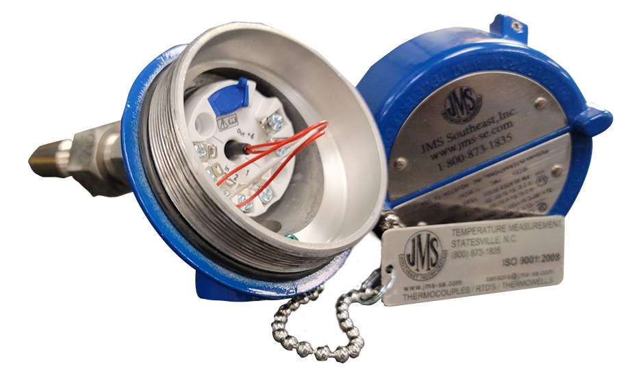
Figure 3. Small loop-powered transmitter mounted on a thermocouple’s connection head. Image used courtesy of JMS Southeast
As mentioned earlier, transmitters are available for many other inputs. Sensor inputs include strain gauge or load cells, potentiometer or slide wire position sensors, pulse rate or frequency from tachometers or motor drives, and others. Some companies provide two-wire transmitters for their chemical sensors. There even are loop-powered flow transmitters. Transmitters with DC millivolt inputs or with DC or AC voltage and current inputs, are all available.
Loop-powered Transmitters With Signal Isolation
Input often must be galvanically isolated from the power and output. This means no electrical connection between the input and the 4-20 mA loop. There are two reasons for this isolation. First, if the output loop is grounded, the input cannot also be grounded. Look again at Figure 2. Circuit common is not the same as the output. If the input common and the negative output are both grounded, they will be connected, shorting out the current sense resistor and creating serious errors. This is a common problem with grounded thermocouple probes.
Second, safety is enhanced with isolation. If the input is a high voltage or high current, it must not be connected to the output loop. Suppose an AC input transmitter is used to monitor power voltage or current. If connected to the output loop, the loop or transmitter might be destroyed. Someone might also be injured or electrocuted.
Fortunately, loop-powered transmitters are available with input/output isolation, as diagrammed in Figure 4. Operation is the same, but isolation is added to the power and signal paths. Power isolation is usually done using transformers. The DC voltage is chopped to make AC, then fed through a transformer and rectified back to DC on the output side.

Figure 4. Block diagram of a loop-powered transmitter with input/output isolation and optional display.
Signals may be isolated in several ways. On older designs, transformer isolation was used, but optocoupler and capacitive isolation are the typical solutions for modern equipment. The conditioned input signal is converted to pulse or frequency modulation, fed through the optocoupler or small high-voltage capacitors, and converted back to DC. Modern transmitters often use microprocessors or microcontrollers instead of all-analog circuitry, making coupled pulses the obvious choice.
Transmitters With LCD Displays
Some transmitters offer optional built-in displays, usually an LCD for minimum current use. Figure 3 includes this option. This is easily accomplished in microcontroller-equipped transmitters, but analog-to-display ICs also may be used.
The display can be scaled to read “engineering units” instead of simply 4-20 mA or 0 percent to 100 percent. Engineering units are the actual process value, such as degrees or kilograms, that represent the physical process. The process value can be seen at the measurement point and in the control room.
Optional Transmitter Features
Some microprocessor-based transmitters can have their ranges changed by the user. HART (Highway Addressable Remote Transducer) transmitters impose digital communication pulses on top of the 4-20 mA, allowing remote recalibration, range change, and other options.
Some transmitters carry approvals supporting use in hazardous (explosive) locations when properly installed in specified systems according to their approvals. These options are beyond the scope of this article.
Two-wire Enclosure and Mounting Styles
Most loop-powered/two-wire transmitters come in three styles:
-
Head mount, as above shown in Figure 3
-
DIN-rail mount, which clips onto standard industrial mounting rails
-
Terminal-block style, which looks like industrial terminal blocks and can be mounted together with them.
Figures 5 through 7 provide a few examples of different loop-powered transmitters.
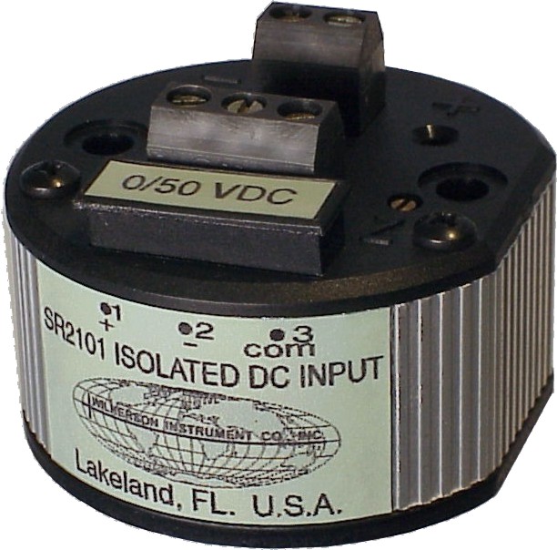
Figure 5. Typical transmitter for mounting in connection head. Image used courtesy of Wilkerson Instrument Company
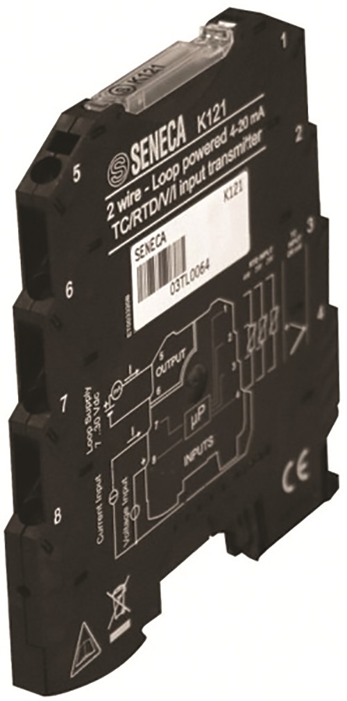
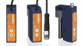
Figure 6. This transmitter can be clipped onto a standard industrial DIN rail. Image used courtesy of Absolute Process Instruments
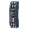
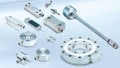
Figure 7. Terminal block style transmitter. Image used courtesy of M-System
Loop-powered Transmitter Suppliers
Process transmitters, both loop-powered and other styles, are available through a mix of sources. Many of the original manufacturers have been bought by and absorbed into larger companies. In the United States, products from other companies are imported and sold by distributors. Here’s a list of suppliers, probably not complete, with web links.
-
Absolute Process Instruments. Manufacturer and distributor. Api-usa.com.
-
Analynk/Telmar. Telmar was once a stand-alone manufacturer. analynk.com/article_74_Telmar-Instruments.cfm.
-
Automation Direct. Distributor. Automationdirect.com. Under Shopping, click Process Control & Measurement, then click Signal Conditioners.
-
Eurotherm/Action Instruments. Action once was a stand-alone manufacturer. Eurotherm.com. Click on Products, then I/O Signal Conditioning.
-
JMS Southeast. Distributor as well as temperature sensor manufacturer. Jms-se.com. Click on Transmitters.
-
M-System. Japanese manufacturer, distributed in the US and worldwide. It is sometimes tricky to get to their English website. Here’s a link: M-System - Total Components Supplier for PA/FA/BA
-
Omega Engineering. Distributor and temperature sensor manufacturer. Omega.com. Under All Products, click Data Acquisition, then Signal Conditioners.
-
PR Electronics. Danish manufacturer with a U.S. office in Chicago. www.prelectronics.com/products/temperature-transmitters/
-
Seneca Instruments. Italian manufacturer. Senecainstruments.com/products.html. Distributed in the United States by Absolute Process Instruments, above.
-
Wilkerson Instrument Company. Manufactures instruments and distributes some other products. Wici.com.
Summary
Loop-powered two-wire transmitters simplify field wiring by needing only one pair of wires for both power and output. Using industry-standard 4-20 mA DC transmission, they are available for a wide variety of sensors and other inputs. Signal isolation and digital display options are also available.