 Facebook
 Google
 GitHub
 Linkedin
FOUNDATION Fieldbus Function Blocks
Data-processing modules within FF systems are known as function blocks. Sometimes these blocks serve merely to catalogue data, while in other instances the blocks execute specific algorithms useful for process measurement and control. These “blocks” are not physical entities, but rather abstract software objects – they exist only as bits of data and instructions in computer memory. However, the blocks are represented on FF computer configuration displays as rectangular objects with input ports on the left-hand side and output ports on the right-hand side. The construction of a working control system comprised of FF devices consists of linking the outputs of certain function blocks with the inputs of other function blocks via configuration software and computer-based tools. This usually takes the form of using a computer to draw connecting lines between the output and input ports of different function blocks.
Analog function blocks versus digital function blocks
Function-block programming in general strongly resembles the design philosophy of legacy analog-based computer systems, where specific functions (addition, subtraction, multiplication, ratio, time-integration, limiting, and others) were encapsulated in discrete operational amplifier circuits, and whole systems were built by connecting function blocks together in whatever patterns were desired to achieve a design goal. Here with Fieldbus programming, the function blocks are virtual (bits and data structures in digital memory) rather than real analog circuits, and the connections between blocks are merely pointer assignments in digital memory rather than actual “patch cable” connections between circuit boards.
An example contrasting analog circuit design with Fieldbus function-block design appears here, both systems selecting the greatest temperature signal to be the output. The system on the left-hand side receives analog voltage signals from three temperature sensors, using a network of operational amplifiers, diodes, and resistors to select the greatest voltage signal to be the output. The system on the right-hand side uses three Fieldbus transmitters to sense temperature, the greatest temperature signal selected by an algorithm (the ISEL function block) running in a Fieldbus device. The device running the ISEL function could be one of the three FF temperature transmitters, or another device on the segment:

Instead of analog voltage signals sent by wire to special-function circuit modules, FOUNDATION Fieldbus uses digital messages sent over an H1 network segment to special-function software “blocks” running inside ordinary Fieldbus devices. The lines connecting different function blocks together in a FOUNDATION Fieldbus system show the sources and destinations of these digital messages. If two FF function blocks reside in different FF devices, the connecting lines represent publisher/subscriber communication assignments coordinated by the Link Active Scheduler (LAS) device.
Function block location
There is usually some freedom of choice in where various function blocks may be located in a FF segment. Take for example the following flow control loop, where a flow transmitter feeds measured flow data into a PID control function block, which then drives a control valve to whatever position necessary to regulate flow. The actual physical device layout might look something like this:

The function block connections necessary for this control scheme to work are shown in the next diagram, coupling the AI (analog input) block located in the transmitter to a PID control block to an AO (analog output) block located in the valve positioner:

All function block inputs are on the left-hand sides of the blocks, and all outputs are on the right-hand sides. In this function block program, data from the analog input (AI) block flows into the PID block. After calculating the proper output value, the PID block sends data to the analog output (AO) block where the final control element (e.g. valve, variable-speed motor) is adjusted. The AO block in turn sends a “back calculation” signal to the PID block to let it know the final control element has successfully reached the state commanded by the PID block’s output. This is important for the elimination of reset windup in the event the final control element fails to respond to the PID block’s output signal.
It should be obvious that the analog input (AI) block must reside in the transmitter, simply because only the transmitter is able to measure the process fluid flow rate. Likewise, it should be obvious that the analog output (AO) block must reside in the control valve positioner, simply because the valve is the only device capable of manipulating (exerting influence over) anything. However, given the lack of a separate controller device, the person configuring the Fieldbus loop may choose to locate the PID block in either the transmitter or the control valve positioner. So long as both the FF transmitter and the FF valve positioner possess PID function block capability, it is possible to locate the PID function block in either device.
The following illustrations show the two possible locations of the PID function block in this system:

The only factor favoring one location over another for the PID function block is the number of communication broadcasts (“Compel Data” token distributions and replies) necessary per macrocycle. Note the lines connecting function blocks between the two instruments in the previous diagrams (lines crossing from one blue bubble to another). Each of these lines represents a VCR (Virtual Communication Relationship) – an instance during each macrocycle where data must be transmitted over the network segment from one device to another. With the PID function block located in the flow transmitter, two lines connect blocks located in different physical devices. With the PID function block located in the valve positioner, only one line connects blocks in different physical devices. Thus, locating the PID function block in the valve positioner means only one CD message/reply is necessary per macrocycle, making the network communication more efficient.
To illustrate the difference this re-location of the PID block makes, we will examine the function block diagram and macrocycle timing schedule on a simple pressure control FF loop, hosted on an Emerson DeltaV distributed control system. The first composite screenshot shows the function block diagram and schedule with the PID function block located in the transmitter (PT_501):


Note the two scheduled communication events (CD tokens and responses) necessary in the macrocycle schedule to enable communication between pressure transmitter PT_501’s PID function block and valve positioner PV_501’s analog output function block. The first CD token in this macrocycle schedule compels the PID block to publish its “output” signal (subscribed to by the analog output block), while the second token compels the analog output block to publish its “back calculation” signal (subscribed to by the PID block). The amount of time required for function block execution and their publisher/subscriber communications is 330 milliseconds, with a total macrocycle time of 1 second.
Now let’s examine the same PID pressure control system with the PID function block moved to the valve. Here you see the function block diagram followed immediately by the updated macrocycle schedule:


In this macrocycle timing schedule, there is only one CD token needed: compelling the analog input block to publish its measurement signal (subscribed to by the PID block). This makes the block execution plus scheduled communication time 30 milliseconds shorter than before (300 milliseconds total as opposed to 330 milliseconds), since there is one less scheduled communications event happening. The total macrocycle time of 1 second remains unchanged, but now we have 30 milliseconds more unscheduled time during which other communication events may take place.
Standard function blocks
The FF standard specifies many different function blocks for the construction of control algorithms. Ten of them are considered “basic” FF function blocks:
AI– Analog InputAO– Analog OutputB– BiasCS– Control SelectorDI– Discrete InputDO– Discrete OutputML– Manual LoaderPD– Proportional/Derivative controlPID– Proportional/Integral/Derivative controlRA– Ratio
Nineteen more “Advanced” function blocks are incorporated in the FF standard:
- Pulse Input
- Complex Analog Output
- Complex Discrete Output
- Step Output PID
- Device Control
- Setpoint Ramp
- Splitter
- Input Selector
- Signal Characterizer
- Dead Time
- Calculate
- Lead/Lag
- Arithmetic
- Integrator
- Timer
- Analog Alarm
- Discrete Alarm
- Analog Human Interface
- Discrete Human Interface
Five more function blocks are specified as well:
- Multiple Analog Input
- Multiple Analog Output
- Multiple Digital Input
- Multiple Digital Output
- Flexible Function Block
The primary benefit of standardization is that the end-user may choose FF instruments manufactured by any standard-compliant vendor, and those function blocks should behave the same as the equivalent function blocks within any other manufacturer’s model of FF device. There are, of course, examples where manufacturers have equipped their FF devices with “extended” capability function blocks going beyond the Fieldbus Foundation standard, and the user must beware of this.
Device-specific function blocks
In addition to the function blocks necessary to construct control schemes, all FF instruments contain one Resource block and usually one or more Transducer blocks describing details specific to that instrument. The following computer screenshot shows all function blocks within a Rosemount model 3095MV Fieldbus transmitter:
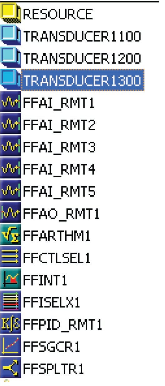
The Resource block appears first in this list, followed by three transducer blocks, then followed by the palette of general function blocks for use in constructing control algorithms. Information contained in the Resource block of an FF instrument includes the following:
- Identifier (the 32-byte code unique to every FF device)
- Type of device
- Device revision level
- Memory total and available (free) capacity
- Computation time
- Available features listing
- Current device state (Initializing, Standby, On-line, Failed, etc.)
Transducer blocks provide a means of organizing data relevant to the actual sensing inputs, outputs, calculated variables, and graphic displays of a FF device. There need not be a one-to-one correspondence between the number of transducer blocks in an FF device and the number of physical I/O channels it has. For example, in the Rosemount 3095MV multivariable transmitter, transducer block 1100 manages all physical measurement inputs (pressure and temperature sensors) while transducer block 1200 is reserved for inferred mass flow (based on calculations performed on the raw sensor measurements) and transducer block 1300 manages data for the liquid crystal display (LCD).
FF signal status
As mentioned earlier, function block programming bears a strong resemblance to analog function-block circuit design, where specific tasks are divided up into discrete elements, those elements connected together to form a larger system with more complex functionality. One of the important distinctions between legacy analog function block circuit design and FF function block programming is the data content of the lines connecting blocks together. In the analog world, each connecting line (wire) carries exactly one piece of information: a single variable represented in analog form by a voltage signal. In the world of Fieldbus, each connecting line carries not only the variable’s numerical value, but also a status and in some cases an engineering unit (a unit of measurement). For example, a Fieldbus transmitter sensing temperature might output a digital process variable (PV) signal of “342 degrees Celsius, Good”, whereas a temperature transmitter with an analog (e.g. 4-20 mA) output is merely able to send a signal representing the temperature (no measurement unit or status information).
The inclusion of status along with data is a powerful concept, with roots in scientific practice. Scientists, as a rule, do their best to report the degree of confidence associated with the data they publish from experiments. Data is important, of course, but so is the degree of certainty with which that data was obtained. Obviously, data gathered with instruments of low quality (high uncertainty) will have different significance than data gathered with instruments of high precision and impeccable accuracy (low uncertainty). Any scientist basing research on a set of scientific data published by another scientist will have access to the data’s certainty in addition to the data itself – a very valuable detail.
By the same token, data “published” by a FF device is only as good as the health of that device. A FF transmitter exhibiting noisy or wildly fluctuating measurements might very well be nearing complete failure, and therefore its published data should be treated with skepticism. Since FF devices are “smart” (meaning, among other things, they have self-diagnostic capability), they have the ability to flag their own data as “Bad” if an internal fault is detected. The data still gets published and sent to other FF function blocks, but the status sent along with that data warns all downstream blocks of its uncertainty.
The three major status conditions associated with every FF signal passed between function blocks are Good, Bad, and Uncertain. Sub-status states also exist to further delineate the nature of the uncertainty. “Sensor Failure” is an example of a sub-status value, describing the reason for a “Bad” status value from a process transmitter.
In computer science, there is a truism that “Garbage In equals Garbage Out,” sometimes abbreviated as GIGO. No algorithm, no matter how advanced, can guarantee an output of good data from an input of bad data. This principle finds intelligent application in FF function block programming, as the blocks are programmed to switch mode when “Bad” or “Uncertain” input statuses are detected. For example, here are some of the possible actions a function block may be configured to take upon detection of a “Bad” input signal status:
- Set output signal to last “Good” value
- Fail high (set output signal to top-of-range value)
- Fail low (set output signal to bottom-of-range value)
Furthermore, status values are propagated in a FF system from the input to the output of every function block connected in series, reflecting the effect of an input signal’s uncertainty throughout the entire control loop. For example, an analog input (AI) block sending a “Bad” status signal to the process variable input of a PID control block will have its “Bad” status propagated to the output of the PID block as well. When that “Bad” PID output signal reaches the analog output (AO) function block, that final block knows the signal is not to be trusted, because its origin (the AI block) is untrustworthy. Any function blocks receiving the PID block’s output signal will likewise sense the “Bad” status and further propagate that status to their output signal(s). This “status propagation” ensures all function blocks in a Fieldbus control system are “aware” of the input data status, so that a “Bad” measurement does not result in “bad” control decisions made on that data.
Function block modes
All FF function blocks must support multiple modes of operation, describing how the block should execute its intended function. Several different function block modes are commonly found for FF function blocks, though not all FF function blocks support all of these modes:
- OOS (Out Of Service) – All function blocks are required to support this mode, where the block freezes its output at the last calculated value and attaches a “Bad” status value
- Man (Manual) – the output of the block is fixed at a value determined by the technician, with a “Good” status value attached
- Auto (Automatic) – the function block processes information normally
- Cas (Cascade) – the function block processes information normally
- Iman (Initialization Manual) – the output of the block is fixed at its last calculated value, due to the output signal path being incomplete
- LO (Local Override) – the output of the block is fixed at its last calculated value, due to a detected fault condition within the device
- RCas (Remote Cascade) – the function block processes information normally based on a setpoint sent from a remote source to the block’s RCas_In input
- ROut (Remote Output) – the function block passes data to its output sent from a remote source to the block’s ROut_In input
Instrumentation technicians and professionals are already familiar with the concept of a controller having “Automatic,” “Manual,” and even “Cascade” operating modes, but Fieldbus function block programming extends this general concept to each and every function block. With FF, each block may be independently set into “Automatic” or “Manual” mode, which is a useful tool for testing FF algorithms and troubleshooting complex FF control schemes. The “Out of Service” mode, for instance, is commonly set when performing routine maintenance on an FF device (e.g. checking the calibration of an FF transmitter).
It is worth noting an important distinction here between Manual mode and OOS (Out Of Service) mode. In both cases, the function block’s output becomes fixed at some value, but a major difference between these two modes is their associated statuses. In Manual mode, the output value is fixed and the status is “Good,” allowing all function blocks downstream to remain operational. In OOS mode, the output value is fixed and the status is “Bad,” causing all downstream function blocks to react as they would when receiving any “Bad” signal status (usually by shedding to Manual mode themselves). Placing a function block in Manual mode is useful when performing tests on the control strategy because it allows the technician or engineer to simulate values that might come from transmitters and other “upstream” devices in the loop. All function blocks receiving a signal from a block in Manual mode will continue to operate as they are designed. However, placing a function block in OOS mode is quite different in that all function blocks receiving that signal will act as though there is a serious problem rather than acting normally.
In addition to these operating modes for FF function blocks (not all of which are supported by all FF blocks), FF function blocks also have four mode categories describing valid modes for the block to be in under various conditions:
- Target
- Actual
- Permitted
- Normal
A block’s “Target” mode is the mode it strives to be in if possible. The “Actual” mode is the mode the block is in at the present time. “Permitted” modes list all the different modes which may be used as “target” modes. “Normal” is a category describing to an operator interface what a block’s normal operation mode should be, but the block itself does not heed this setting.
