 Facebook
 Google
 GitHub
 Linkedin
FOUNDATION Fieldbus H1 Protocol Data Link Layer
Like so many other industrial data networks, FOUNDATION Fieldbus is an “unswitched” or “broadcast” type of network. This means all data transmissions by all devices on a network are sensed by all the other devices. In other words, there are no private messages between two devices on a shared network: every device “hears” every transmission from every other device. This means devices must take turns communicating, with no simultaneous transmissions. Layer 2 of the OSI Reference Model is where we define the “data link” elements of a digital data network, describing how individual devices negotiate for the right to transmit on the network. Here is a list of some layer-2 properties of H1 FF networks:
- Master/slave network behavior for cyclic communications (i.e. one device polls the others, and the others merely respond)
- Delegated token network behavior for acyclic communications (i.e. devices serially granted time to broadcast at will)
- Dedicated “scheduler” device for coordinating all segment communications
- 8-bit address field (0 through 255 possible)
- Maximum of 32 “live” devices on a segment
On an operating H1 segment, one device called the Link Active Scheduler (abbreviated LAS) functions as the “master” device for coordinating all network communications, analogous to a police officer directing traffic in a road intersection. The LAS device may be a regular field instrument (e.g. transmitter, valve positioner) or it may be the host system (i.e. the H1 segment interface card of a DCS). The FF standard allows for one operating LAS device, with multiple back-up LAS devices waiting to take over if the primary LAS happens to fail for any reason.
One of the tasks of the LAS is to “compel” the various field instruments to transmit their process control data (process variables, PID control output values, and other variables essential for loop monitoring and control), while the devices immediately respond in answer to the LAS’s “compel data” command. These critical communications occur on a regular schedule, and therefore are referred to as scheduled or cyclic communications. Cyclic communication operates in a “master-slave” fashion, with the LAS acting as the master (commanding slave devices to broadcast specific data), and all other devices responding only when called upon by the LAS. This form of communication is analogous to a traffic officer specifically directing one vehicle at a time to drive through an intersection in a prescribed manner.
Periods of time in between these critical transmissions on an H1 network are used for device’s internal processing (e.g. PID algorithm execution, diagnostic checking) and also for less-critical data transmission. It is during these unscheduled or acyclic times that devices are sequentially permitted (but not compelled) by the LAS to broadcast data of less importance such as operator setpoints, PID tuning constant updates, alarm acknowledgments, and diagnostic messages. This form of communication is analogous to a traffic officer directing an entire lane of vehicles to enter the intersection at will.
The scheduled nature of cyclic communication guarantees a certain maximum response time to critical control functions, an important property of control networks called determinism. Without determinism, a control system cannot be relied upon to perform critical regulatory functions in a timely manner, and sequencing of control functions such as PID, summers, subtractors, ratio multipliers, and the like may be compromised. Thus, all the critical variables of a FF H1 loop are communicated between devices this way.
Device addressing
FOUNDATION Fieldbus devices (also called nodes) are addressed by an eight-bit binary number when functioning on an H1 segment. This binary number field naturally supports a maximum addressing range of 0 to 255 (decimal), or 00 to FF hexadecimal. This address range is divided into the following sub-ranges by the Fieldbus Foundation:
(decimal) & (hexadecimal) & \cr
| Address range | Address range | Allocation |
|---|---|---|
| 0 through 15 | 00 through 0F | Reserved |
| 16 through 247 | 10 through F7 | Permanent devices |
| 248 through 251 | F8 through FB | New or decommissioned devices |
| 252 through 255 | FC through FF | Temporary (``visitor'') devices |
Devices are usually assigned addresses to function on the segment by the host system (typically a DCS with FF capability), although it is possible to order FF instruments pre-configured at the factory with addresses specified by the customer upon order. Host systems are generally configured to automatically determine device addresses rather than require the technician or engineer to manually assign each address. This makes the commissioning process more convenient.
The maximum number of “permanent” devices (installed field instruments) allowed on an H1 segment for operational reasons is 32, and as you can see the addressing scheme offers far more valid addresses than that. One of the many tasks given to a segment’s Link Active Scheduler (LAS) device is to probe for new devices connected to the segment. This is done on a one-at-a-time basis, with the LAS sequentially polling for uncommissioned addresses within the valid address range. Obviously, this can be a waste of time with only 32 addresses capable of active service at any given time and over 200 valid address numbers. A practical solution to this problem is to specify an “unused” address range for the LAS to skip, so it does not waste time probing for devices (nodes) within a certain range. This address range is specified as a set of two numbers: one for the First Unused Node (abbreviated FUN), and another specifying the Number of Unused Nodes (abbreviated NUN). For example, if one wished to have the LAS on a particular H1 segment skip device addresses 40 through 211, one would configure the FUN to equal 40 and the NUN to equal 172, since the address range 40 through 211 is one hundred seventy two addresses (inclusive of both 40 and 211).
Even with a maximum operational limit of 32 devices to an H1 segment, it is rare to find segments operating with more than 16 devices. One reason for this is speed: with additional devices requiring time to broadcast and process data, the total macrocycle time (the time period between guaranteed delivery of the same process data from any one device – the determinism time) must necessarily increase. According to the Fieldbus Foundation’s engineering recommendations guide, there must be no more than twelve devices on a segment (including no more than two final control elements) in order to achieve a 1-second or less macrocycle time. For half-second update times, the recommended maximum is six devices (with no more than two final control elements). For quarter-second update times, the limit drops to a total of three devices, with no more than one final control element. Macrocycle time is essentially dead time, which is worse than lag time for any form of feedback control. When controlling certain fast processes (such as liquid pressure or flow rate), dead times on the order of one second are a recipe for instability.
Another limitation to the number of operational addresses on an H1 segment is current draw. FF devices draw 10 mA of current minimum. A FF segment with sixteen parallel-connected devices would see a total current of 160 mA minimum, with a more realistic value being in excess of 300 mA.
In addition to network addresses, each FF device bears an absolutely unique identifier (a 32-byte binary number) to distinguish it from any other FF device in existence. This identifier serves much the same purpose as a MAC address on an Ethernet device. However, the identifier field for FF devices allows a far greater instrument count than Ethernet: 32 bytes for FF instruments versus 48 bits for Ethernet devices. While the Ethernet MAC address field only allows for a paltry \(2.815 \times 10^{14}\) unique devices, the FF identifier allows \(1.158 \times 10^{77}\) devices! The distinction between a FF device’s network address and the device’s identifier is virtually identical to the distinction between an Ethernet device’s IP address assigned by the end-user and its MAC address number assigned by the manufacturer.
This identifier value is usually expressed as 32 ASCII-encoded characters for brevity (one alphanumeric character per byte), and is subdivided into byte groups as follows:
| First 6 bytes | Middle 4 bytes | Last 22 bytes |
|---|---|---|
| Manufacturer code | Device type code | Serial number |
For example, the identifiers for all Fisher brand devices begin with the first six characters 005100. The identifiers for all Smar devices begin with the characters 000302. The identifiers for all Rosemount brand devices begin with 001151. A typical identifier (this particular one for a Fisher model DVC5000f valve positioner) appears here:
\[\hbox{\texttt{005100 0100 FISHERDVC0440761498160}}\]
Normally, these identifiers appear as 32-character strings, without spaces at all. I have inserted spaces within this string to make the character groupings easier to see.
Communication management
In a FF network segment, the Link Active Scheduler (LAS) device coordinates all communications between segment devices. Among the many responsibilities the LAS is tasked with are the following:
- Commands non-LAS devices to broadcast data to the segment with “Compel Data” (CD) messages, issued at regular time intervals to specific devices (one at a time)
- Permits non-LAS devices to voluntarily communicate with “Pass Token” (PT) messages, issued during unscheduled time slots to specific devices (one at a time, in ascending order of address number)
- Keeps all segment devices synchronized with a regular “Time Distribution” (TD) message
- Probes for new devices on the segment with a “Probe Node” (PN) message
- Maintains and publishes a list of all active devices on the network (the Live List)
Scheduled versus unscheduled communication
As previously mentioned, Fieldbus H1 network communication may be divided into two broad categories: scheduled (cyclic) and unscheduled (acyclic). Scheduled communication events are reserved for exchanging critical control data such as process variable measurements, cascaded setpoints, and valve position commands. These scheduled communications happen on a regular, timed schedule so that loop determinism is guaranteed. Unscheduled communications, by contrast, are the way in which all other data is communicated along an H1 segment. Manual setpoint changes, configuration updates, alarms, and other data transfers of lesser importance are exchanged between devices in the times between scheduled communication events.
Both forms of communication are orchestrated by the Link Active Scheduler (LAS) device, of which there is only one active at any given time on an H1 segment. The LAS issues “token” messages to non-LAS devices commanding (or merely authorizing) them to broadcast to the segment one at a time. Each token message issued by the LAS confers transmission rights to an FF device either for a limited purpose (i.e. the precise message to be transmitted) or for a limited time (i.e. giving that device the freedom to transmit whatever data it desires for a short duration), after which transmission rights return to the LAS.
CD tokens are both compulsory and message-specific: each one issued by the LAS commands a single device to immediately respond with a broadcast of some specific data. This is how scheduled (cyclic) communication is managed, intended for the deterministic communication of critical data necessary for automatic process control functions. By contrast, PT tokens are both voluntary and time-specific: each one issued by the LAS grants a single device free time to transmit data of lesser importance. This is how unscheduled (acyclic) communication between devices is managed, intended for the non-deterministic communication of status messages and human interactions with the control system (e.g. mode changes, maintenance, alarms, parameter adjustments).
The LAS also issues a third type of token message: the “Probe Node” (PN) token intended to elicit a response from any new devices connected to the network segment. Probe Node tokens are issued one at a time to each uncommitted device address in search of any new devices.
In addition to transmitting tokens – which by definition are messages granting another device permission to transmit to the network – the LAS also broadcasts other messages necessary for the function of an H1 segment. For example, the “Time Distribution” (TD) message regularly broadcast by the LAS keeps all devices’ internal clocks synchronized, which is important for the coordinated transfer of data.
One of the “internal” tasks of the LAS not requiring network broadcasts is the maintenance of the Live List, which is a list of all known devices functioning on the network segment. New devices responding to “Probe Node” messages will be added to the Live List when detected. Devices failing to return or use PT tokens issued to them are removed from the Live List after a number of attempts. When “backup” LAS devices exist on the segment, the LAS also publishes updated copies of the Live List to them, so they will have the most up-to-date version should the need arise to take over for the original LAS (in the event of an LAS device failure).
In “busy” H1 segments where multiple devices are exchanging data with each other, a heavy traffic load of scheduled communications (CD tokens and their responses) makes it difficult for substantial unscheduled (acyclic) data exchanges to occur. For example, if a device happens to be maintaining a lengthy list of client/server requests in its queue, which it may address only during its allotted acyclic time slots (i.e. when it has been given the PT token from the LAS), it is quite possible the PT token will expire before all the device’s transactions have been completed. This means the device will have to wait for the next acyclic period before it can complete all the unscheduled communication tasks in its queue. The Fieldbus Foundation recommends new H1 segments be configured for no more than 30% scheduled communications during each macrocycle (70% unscheduled time). This should leave plenty of “free time” for all necessary acyclic communications to take place without having to routinely wait multiple macrocycles.
Virtual Communication Relationships
A term you will frequently encounter in FF literature is VCR, or “Virtual Communication Relationship.” There are three different types of VCRs in FF, describing three different ways in which data is communicated between FF devices:
- Publisher/Subscriber (scheduled), otherwise known as Buffered Network-scheduled Unidirectional (BNU)
- Client/Server (unscheduled), otherwise known as Queued User-triggered Bidirectional (QUB)
- Source/Sink (unscheduled), otherwise known as Queued User-triggered Unidirectional (QUU)
: this VCR describes the action of a Compel Data (CD) token. The Link Active Scheduler (LAS) calls upon a specific device on the network to transmit specific data for a time-critical control purpose. When the addressed device responds with its data, multiple devices on the network “subscribing” to this published data receive it simultaneously. This is how process-control variables (PV, PID output, etc.) are communicated between instruments comprising a FF control loop. The publisher/subscriber VCR model is highly deterministic because all such communications occur on a precisely defined schedule.
: this VCR describes one class of unscheduled communications, permitted when a device receives a Pass Token (PT) message from the LAS. Each device maintains a queue (list) of data requests issued by other devices (clients), and responds to them in order as soon as it receives the Pass Token. By responding to client requests, the device acts as a server. Likewise, each device can use this time to act as a client, posting their own requests to other devices, which will act as servers when they receive the PT token from the LAS. This is how non-critical messages such as maintenance and device configuration data, operator setpoint changes, alarm acknowledgments, PID tuning values, etc. are exchanged between devices on an H1 segment. Trend data (process variables recorded over time and displayed in time-domain graph form) may also be communicated using this type of VCR, with a “burst” of collected samples communicated per server message. Client/server communications are checked for data corruption by their receivers, to ensure reliable data flow.
(also called ): this VCR describes another class of unscheduled communications, permitted when a device receives a Pass Token (PT) message from the LAS. This is where a device broadcasts data out to a “group address” representing many devices. Source/sink communications are not checked for data corruption, as are client/server communications. Examples of messages communicated in a FF segment using the source/sink VCR include trend reports and alarms.
An analogy for making sense of VCRs is to imagine lines drawn between FF devices on a segment to connect their various messages to other devices. Each line represents an individual transmission which must take place some time during the macrocycle. Each line is a VCR, some managed differently than others, some more critical than others, but all of them are simply communication events in time. A specific example of this is in the function block diagrams for a FF control system, where connecting lines between function blocks residing in different devices represent messages sent by the Publisher/Subscriber VCR method. Each line connecting function blocks between different devices is a message in response to a CD (Compel Data) token issued by the LAS, ensuring the deterministic transfer of critical control data between function blocks necessary for the control system to reliably function.
For example, consider this H1 segment connected to an interface card on a DCS rack, followed by a P&ID showing the relationships between the instruments:

Loop 211 is a simple PID level control, regulating liquid level in the reactor vessel by releasing liquid from the bottom. Loop 187 is a simple indicating/recording system for temperature and flow, the signals coming from a multivariable transmitter. Loop 231 is a cascaded pressure/flow control system, with reactor pressure as the master variable and feed flow as the slave variable: the pressure controller (residing inside pressure transmitter PT-231) provides remote setpoint values to the flow controller (residing in the flow control valve FV-231), which then adjusts the position of the valve to achieve the desired feed flow rate into the reactor until reactor pressure stabilizes at setpoint.
Note the different line types used to represent digital signals in the P&ID: lines with diamond symbols represent data sent over Fieldbus cable, while lines with hollow circles represent data sent between functions within the same physical device. These latter “internal” data links help the reader discern which functions reside in which physical instruments. Functions residing within the same FF device must also share the same loop number. These standards for P&ID notation come from the Fieldbus Foundation’s System Engineering Guidelines document (revision 2.0, page 72) and from the ANSI/ISA-5.1-2009 “Instrumentation Symbols and Identification” standard.
For example, the PID control function represented by FC-231 resides within the valve positioner (FV-231), because those two bubbles share the same loop number and are connected with lines having hollow circles (which means they are parts of one homogeneous system rather than independent instruments). Likewise, the same line symbology tells us that pressure control PID function PC-231 resides within the pressure transmitter PT-231.
Control-critical variables communicated over the segment between devices include the output value of PC-231 (cascade flow controller FC-231’s remote setpoint value), flow transmitter FT-231’s process variable measurement, and the process variable from level transmitter LT-211. These are all Publisher/Subscriber VCRs, transmitted at the request of a Compel Data (CD) token issued by the LAS device on a tightly controlled schedule. PC-231, FT-231, and LT-211 publish their data to the H1 segment one at a time (each broadcast at the command of a separate CD token issued by the LAS), with FC-231 subscribing to PC-231’s and FT-231’s data, and LC-211 subscribing to LT-211’s data:

Messages such as operator-adjusted setpoint values and maintenance tasks occur as Client/Server VCRs, done during the “unscheduled” communication times in the LAS’s sequence. The LAS device issues Pass Token (PT) messages to each device, giving permission for each device (one at a time) to transmit such information as necessary. Examples of such non-critical messages in our reactor control system are shown here:

In this example, LC-211 is a client to the operator’s display console which serves setpoint and tuning parameter data to that controller. Likewise, PC-231 is a client receiving setpoint data served by the operator console. FT-187 is a client to either a portable Fieldbus communication device or to an engineering workstation in the control system where a technician serves new process variable range parameters to it.
Finally, our third VCR (Source/Sink) finds application in the reactor control system for flow transmitter FT-187, broadcasting its flow trend data during “unscheduled” periods in the LAS’s cycle, as well as for instrument alarm messages. Like the Client/Server messages, this one is prompted when the device receives a special Pass Token (PT) signal from the LAS, giving temporary permission for that device to broadcast its data:
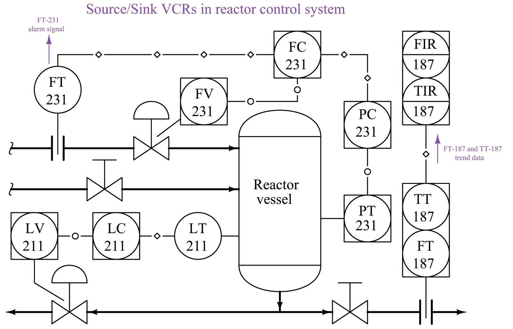
In this example, we see FT-231 sourcing an alarm message to an operator console which functions as a sink for that data. Likewise, TT-187 and FT-187 both source trend data while TIR-187 and FIR-187 sink that data, respectively.
Device capability
Not all FF devices are equally capable in terms of Data Link (layer 2) functions. The FF standard divides data link device functionality into three distinct groups, shown here in order of increasing capability:
- Basic devices
- Link Master devices
- Bridge devices
A Basic device is one capable of receiving and responding to tokens issued by the Link Active Scheduler (LAS) device. As discussed previously, these tokens may take the form of Compel Data (CD) messages which command immediate response from the Basic device, or Pass Token (PT) messages which grant the Basic device time-limited access to the segment for use in broadcasting data of lesser importance.
A Link Master device is one with the ability to be configured as the LAS for a segment. Not all FF devices have this ability, due to limited processing capability, memory, or both.
A Bridge device links multiple H1 segments together to form a larger network. Field instruments are never Bridge devices – a Bridge is a special-purpose device built for the express purpose of joining two or more H1 network segments.
