 Facebook
 Google
 GitHub
 Linkedin
FOUNDATION Fieldbus H1 Protocol Physical Layer
Layer 1 of the OSI Reference Model is where we define the “physical” elements of a digital data network. The H1 FF network exhibits the following properties:
- Two-wire (ungrounded) network cable
- 100 ohm (typical) characteristic impedance
- DC power is conveyed over the same two wires as digital data
- 31.25 kbps data rate
- Differential voltage signaling (0.75 volts peak-to-peak transmit minimum ; 0.15 volts peak-to-peak receive threshold minimum)
- Manchester encoding
Since DC power is conveyed over the same two wires as the digital data, it means each device only needs to connect to two wires in order to function on an H1 network segment. The choice of a (relatively) slow 31.25 kbps data rate allows for imperfect cables and terminations which would otherwise plague a faster network. Manchester encoding embeds the network clock pulse along with the digital data, simplifying synchronization between devices.
As you can see, the layer 1 design parameters were chosen to make FF H1 networks easy to build in unforgiving industrial environments. The physical layer of FOUNDATION Fieldbus happens to be identical to that of Profibus-PA, further simplifying installation by allowing the use of common network validation tools and connection hardware.
Segment topology
A minimal FF H1 segment consists of a DC power supply, a “power conditioner,” exactly two terminator resistors (one at each extreme end of the cable), a shielded and twisted-pair cable, and of course at least two FF instruments to communicate with each other. The cable connecting each instrument to the nearest junction is called a spur (or sometimes a stub or a drop), while the cable connecting all junctions to the main power source (where a host DCS would typically be located) is called a trunk (or sometimes a home run for the section leading directly to a host system):

The power conditioner shown in this diagram is a simplified model of the actual device, the function of which being to filter out digital data pulses from reaching the DC power supply. Commercially-available Fieldbus power conditioners are complex electronic circuits rather than passive filter networks.
Normally, we would find more than two FF devices connected to a trunk cable, as well as a “host” system such as a DCS FF card for accessing FF instrument data, performing maintenance tasks, and integrating with other control loops. Regardless of how many (or how few) FF devices connect to an H1 segment, though, there should always be exactly two terminating resistors in each segment – one at each end of the trunk cable. These resistor/capacitor networks serve the sole purpose of eliminating signal reflections off the ends of the trunk cable, making the cable look infinitely long from the perspective of the propagating pulse signals. Missing terminators will result in signal reflections off the unterminated line end(s), while extra terminators have the equally deleterious effect of attenuating signal strength (as well as potentially causing signal reflections of opposite phase).
All H1 networks are essentially parallel electrical circuits, where the two connection terminals of each field instrument are paralleled to each other. The physical arrangement of these transmitters, though, may vary substantially. The simplest way to connect FF H1 devices together is the so-called “daisy-chain” method, where each instrument connects to two cable lengths, forming an uninterrupted “chain” network from one end of the segment to the other:
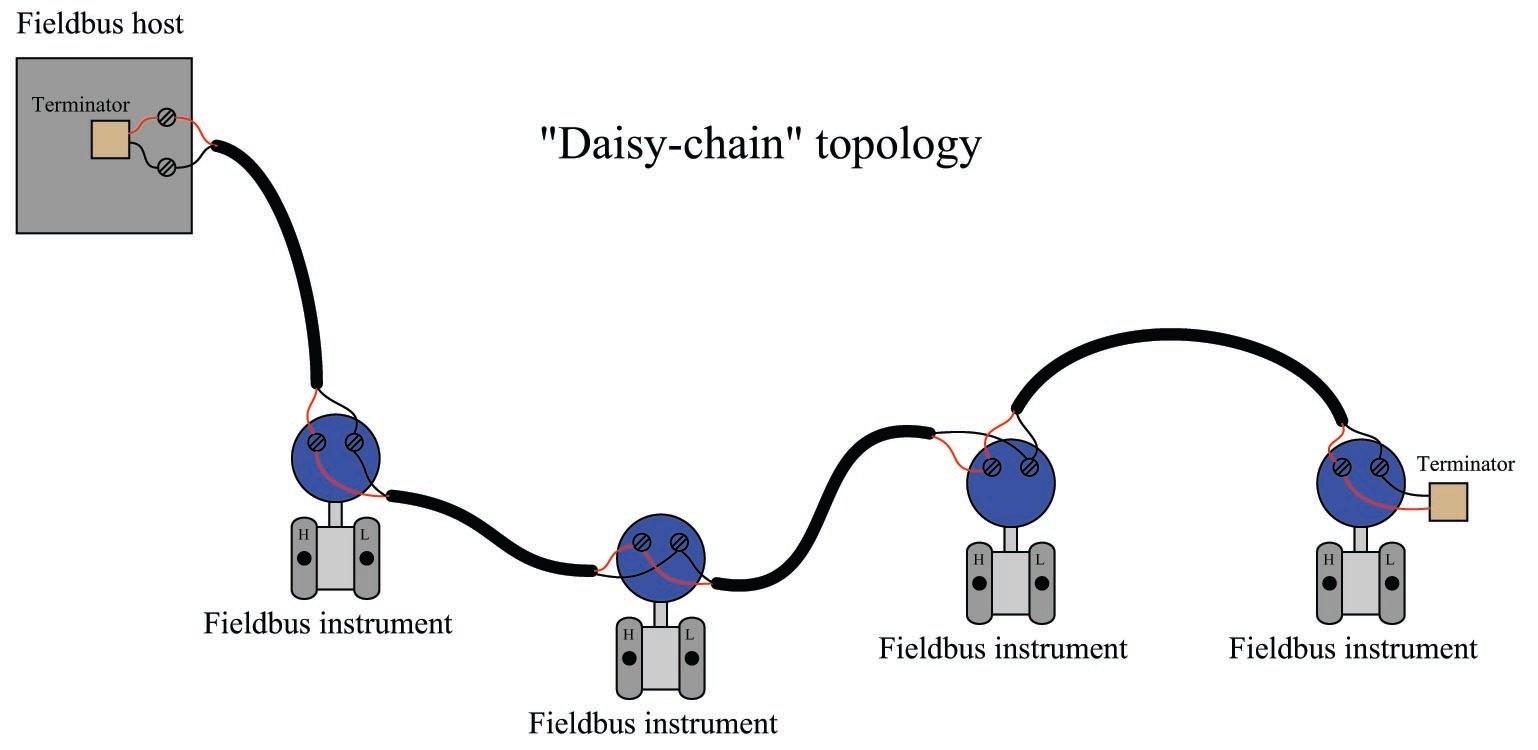
As simple as this topology is, it suffers from a major disadvantage: it is impossible to disconnect any device in the segment without interrupting the network’s continuity. Disconnecting (and reconnecting for that matter) any device necessarily results in all “downstream” devices losing signal, if only for a brief time. This is an unacceptable liability in most industrial applications, as it complicates maintenance and servicing of individual instruments on the segment.
An alternative topology is the bus layout, where short “spur” cables connect instruments to a longer “trunk” cable. Terminal blocks – or even quick-disconnect couplings – within each junction box provide a convenient means of disconnecting individual devices from the segment without interrupting data communication with the other devices:

The ideal arrangement for a “bus” network is to minimize the length of each spur cable, so as to minimize the delay of reflected signals off the unterminated ends of the drops. Remember that only two termination resistors are allowed in any electrically continuous network segment, and so this rule forbids the addition of terminators to the end of each spur cable.
Yet another alternative topology for H1 networks is the so-called chicken-foot arrangement, where a long trunk cable terminates at a multi-point junction along with several field devices and their spur cables:

Most FF systems resemble a combination of “bus” and “chicken-foot” topologies, where multiple junction devices serve as connection points for two or more field instruments per junction.
Coupling devices
In order to simplify the task of connecting Fieldbus devices to such a network segment, multiple manufacturers sell coupling devices (often informally referred to as bricks) with quick-disconnect electrical fittings so the end-user does not have to build and commission junction boxes using standard terminal blocks. A photograph of a Turck brand Fieldbus coupling device appears here, showing multiple spur cables plugged into it:

Coupling devices are highly recommended for all industrial fieldbus systems, FF or otherwise. Not only do these devices provide a convenient means of forming highly reliable connections between field instruments and the trunk cable, but many of them are equipped with features such as short-circuit protection (so that a shorted spur cable or field instrument does not cause the entire segment to stop communicating) and LED indication of spur status.
Cables connecting to a coupling device must be equipped with special plugs matching the sockets on the coupler. This presents a bit of a problem when attempting to pull such a cable through electrical conduit: the bulky plug requires either over-sized conduit to accommodate the plug’s width, or requires the plug be installed on the cable after pulling through the conduit. Both approaches are expensive, the first in terms of capital cost and the second in terms of installation labor. For this reason, many installers abandon electrical conduit altogether in favor of ITC (“Instrument Tray Cable”).
A wider-angle photograph of the coupling device previously shown reveals many ITC cables and their routing through wire “basket” style trays among process instruments and vessels:

As evident in this photograph, ITC is obviously rated for continuous exposure to direct sunlight and moisture, as well as a certain amount of physical distress (abrasion, high and low temperatures, etc.). Article 727 of the National Electrical Code (NEC) defines the acceptable uses and installations of ITC.
It should be noted that while a properly shielded and grounded FF cable is quite resistant to radio-frequency interference, coupling devices may present “weak spots” where radio interference may find its way onto the segment. Different styles of coupling devices offer differing levels of immunity to RF (Radio Frequency) noise. Those made of metal and properly bonded to ground will be well-shielded, while those made of plastic having exposed connection terminals offer little or no protection. In any case, it is a good practice to avoid “keying” any portable radio transmitter in the near vicinity of a Fieldbus coupling device.
Not all Fieldbus couplers are rated for outdoor installation. Some are intended for mounting inside electrical enclosures, such as this Pepperl+Fuchs model shown mounted on a DIN rail:

This Fieldbus coupling device is aptly labeled a segment protector, for it not only couples spurs to the main trunk of the Fieldbus segment, but it also guards against short-circuits in the spur cables and devices from interrupting communication on the rest of the segment. If you look closely at the upper-left of the coupling device, you will see a black plastic square with two leads inserted into screw terminals: this is one of two terminating resistors found in this Fieldbus segment, meaning this particular coupling device is at the “end of the line” of the network segment.
Not only do enclosure-protected coupling devices eliminate the need for special weather-proof connectors and instrument tray cable, but they also enjoy the radio interference immunity granted by being inside a metal cocoon.
Electrical parameters
FOUNDATION Fieldbus H1 networks use Manchester encoding to represent bit states: a “high-to-low” transition represents a logical zero (0), while a “low-to-high” transition represents a logical one (1). The following illustration shows how the data stream 00100 would be represented in Manchester encoding:

FF devices must be able to correctly distinguish between rising- and fall-edge signals in order to properly interpret the bit states of a Manchester-encoded signal. Any device interpreting these pulse edges “backwards” will invert every single bit! Thankfully, this problem is easy to avoid because the DC power supplied by the H1 segment wiring provides a “key” to identifying which wire is which, and therefore which pulses are rising-edge versus which pulses are falling-edge. For this reason, many (but not all!) FF devices are polarity-insensitive, automatically detecting the polarity of the network segment and compensating accordingly.
Every FF device draws at least 10 mA of current from the segment, and this current does not vary in the same manner that an analog (4-20 mA) device draws differing amounts of current under different operating conditions. Always remember that a Fieldbus device signals its variable(s) digitally, not by varying current. Old habits (and thought patterns) die hard, and so Fieldbus systems present challenges to technicians familiar with the behavior of analog current loop instrumentation. The amount of current drawn by any particular FF device depends on that device’s functionality – obviously, some will require more current for their operation than others. 10 mA to 30 mA should be considered a general range of current drawn by each FF device.
The standard operating voltage range for FF devices is between 9 and 32 volts DC. It is important to note, however, that not all manufacturers’ devices are in full compliance with the Fieldbus Foundation standard, and as such some may not operate properly at low voltages (near 9 volts DC)! The most common DC operating voltage for a FF network segment is 24 VDC (typical).
The minimum transmission voltage of a FF device is 750 millivolts peak-to-peak, while the minimum signal level for reception by a FF device is 150 millivolts peak-to-peak. This represents an acceptable attenuation of 5:1, or \(-14\) dB between any two devices.
Cable types
Fieldbus cable is rated according to a four-level code (A, B, C, or D), each successive letter representing a cable of lower quality. The following table gives minimum specifications for each FF cable type:
| Cable Type | Type A | Type B & Type C & Type D | ||
|---|---|---|---|---|
| Wire size | AWG 18 | AWG 22 | AWG 26 | AWG 16 |
| Char. Impedance | 100 $\Omega$ $\pm$ 20\% | 100 $\Omega$ $\pm$ 30\% | -- | -- |
| Shielding | 1 for each pair | 1 for entire cable | none | none |
| Twisted pairs | Yes | Yes | Yes | No |
| Max. length | 1900 m | 1200 m | 400 m | 200 m |
Bear in mind that the maximum length given for each cable type is the total length of all cables in a segment, trunk length plus all spur lengths. As a general rule, spur lengths should be kept as short as possible. It is better to route the trunk cable in a serpentine fashion to locate coupling devices close to their respective instruments than it is to streamline the trunk cable routing. The following illustrations contrast the two approaches:


If greater lengths are required for a network segment, devices known as repeaters may be added which sense and re-broadcast the Manchester-encoded FF signal between trunk cables. A maximum of four repeaters may be used to extend any H1 segment.
As always, neat wiring practices help make an instrument system easier to maintain and to diagnose when things go wrong. The following photograph shows a triad of FOUNDATION Fieldbus junction boxes and (orange) network cables. Coupling devices located inside each enclosure link each spur cable to the trunk:

Segment design
In addition to maximum (total) cable length and repeater count, a host of other details conspire to limit how any particular H1 segment is wired. To help engineers and technicians alike deal with these details, manufacturers often provide free segment design tool software to pre-validate a segment design on computer before purchasing components and installing them in the field. A screenshot taken from Emerson’s offering shows what a typical FF segment layout might look like:

A very nice feature of these segment design packages is their built-in database of FF components. Every time you “pick” a particular component to place in your simulated segment, the program references data for that device’s current draw and other electrical parameters relevant to the performance of the segment. Of course, each manufacturer will tend to feature their own devices more prominently, and so these software tools sometimes feel like a promotional advertisement. Despite the commercial aspect of their design, however, they are extremely useful in the planning stages of a FF network, and should be used whenever possible.
Another reason to use segment design tool software is to document the wiring of each FF segment. One of the casualties of the new Fieldbus paradigm is the traditional loop diagram (or “loop sheet”), the purpose of which is to document the signal wiring dedicated for each measurement and control loop. In FOUNDATION Fieldbus, the control “loop” is virtual rather than physical, being comprised of digital data sent between field instruments, the path of which being defined by the instruments’ programming. The only physical wiring entity to document in a FF system is the segment, and each segment most likely hosts more than one measurement and/or control loop. Unless and until a standardized documentation format is invented for Fieldbus network segments, the graphic image provided by segment design tool software is as good as anything.
