 Facebook
 Google
 GitHub
 Linkedin
Logic Programming in PLCs

Most PLC programming consists of input contacts and output coils arranged in logical series/parallel combinations to influence real-world outcomes.
Although it seems each model of PLC has its own idiosyncratic standard for programming, there does exist an international standard for controller programming that most PLC manufacturers at least attempt to conform to. This is the IEC 61131-3 standard, which will be the standard presented in this chapter.
One should take solace in the fact that despite differences in the details of PLC programming from one manufacturer to another and from one model to another, the basic principles are largely the same. There exist much greater disparities between different general-purpose programming languages (e.g. C/C++, BASIC, FORTRAN, Pascal, Java, Ada, etc.) than between the programming languages supported by different PLCs, and this fact does not prevent computer programmers from being “multilingual.” I have personally written and/or analyzed programs for over a half-dozen different manufacturers of PLCs (Allen-Bradley, Siemens, Square D, Koyo, Fanuc, Moore Products APACS and QUADLOG, and Modicon), with multiple PLC models within most of those brands, and I can tell you the differences in programming conventions are largely insignificant. After learning how to program one model of PLC, it is quite easy to adapt to programming other makes and models of PLC. If you are learning to program a particular PLC that does not exactly conform to the IEC 61131-3 standard, you will still be able to apply every single principle discussed in this chapter – the fundamental concepts are truly that universal.
The IEC 61131-3 standard specifies five distinct forms of programming language for industrial controllers:
-
Ladder Diagram (LD)
-
Structured Text (ST)
-
Instruction List (IL)
-
Function Block Diagram (FBD)
-
Sequential Function Chart (SFC)
Not all programmable logic controllers support all five language types, but nearly all of them support the Ladder Diagram (LD), which will be the primary focus of this book.
Programming languages for many industrial devices are limited by design. One reason for this is simplicity: any programming language simple enough in structure for someone with no formal computer programming knowledge to understand is going to be limited in its capabilities. Another reason for programming limitations is safety: the more flexible and unbounded a programming language is, the more potential there will be to unintentionally create complicated “run-time” errors when programming. The ISA safety standard number 84 classifies industrial programming languages as either Fixed Programming Languages (FPL), Limited Variability Languages (LVL), or Full Variability Languages (FVL). Ladder Diagram and Function Block Diagram programming are both considered to be “limited variability” languages, whereas Instruction List (and traditional computer programming languages such as C/C++, FORTRAN, BASIC, etc.) are considered “full variability” languages with all the attendant potential for complex errors.
Relating I/O Status to Virtual Elements
Perhaps the most important yet elusive concept to grasp when learning to program PLCs is the relationship between the electrical status of the PLC’s I/O points and the status of variables and other “elements” in its programming. This is especially true for Ladder Diagram (LD) programming, where the program itself resembles an electrical diagram. Making the mental connection between the “real” world of the switches, contactors, and other electrical devices connected to the PLC and the “imaginary” world of the PLC’s program consisting of virtual contacts and relay “coils” is most fundamental.
The first fundamental rule one should keep in mind when examining a Ladder Diagram PLC program is that each virtual contact shown in the program actuates whenever it reads a “1” state in its respective bit and will be at rest whenever it reads a “0” state in its respective bit (in the PLC’s memory). If the contact is a normally-open (NO) type, it will open when its bit is 0 and close when its bit is 1. If the contact is a normally-closed (NC) type, it will close when its bit is 0 and open when its bit is 1. A 0-bit state causes the contact to be in its “normal” (resting) condition, while a 1-bit state actuates the contact, forcing it into its non-normal (actuated) state.
Another rule to remember when examining a Ladder Diagram PLC program is that the programming software offers color highlighting to display the virtual status of each program element: a colored contact is closed, while an un-colored contact is open. While the presence or absence of a “slash” symbol marks the normal status of a contact, its live color highlighting shown by PLC programming software reveals the “conductive” status of the elements in real-time.
Normally Open (XIC) and Normally Closed (XIO)
The following image shows the two types of contacts in a PLC’s Ladder Diagram program.
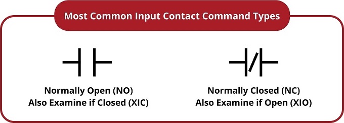
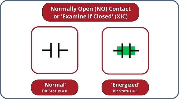
The normally open contact will logically conduct, or become 'closed' when the bit status is a 1, as shown below. As mentioned previously, a logically conducting, or 'closed' element is colored in most ladder programs.
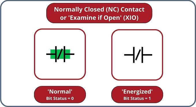
The normally closed contact will logically conduct, or become 'closed' when the bit status is a 0, as shown below.
Just as a pressure switch’s contacts are actuated by a high-pressure condition, and a level switch’s contacts are actuated by a high-level condition, and a temperature switch’s contacts are actuated by a high-temperature condition, so a PLC’s virtual contact is actuated by a high bit condition (1). In the context of any switch, an actuated condition is the opposite of its normal (resting) condition.
The following simplified illustration shows a small PLC with two of its discrete input channels electrically energized, causing those two bits to have “1” statuses. The color-highlighted contacts in the programming editor software’s display shows a collection of contacts addressed to those input bits in various states (colored = closed; un-colored = open). As you can see, every contact addressed to a “set” bit (1) is in its actuated state, while every contact addressed to a “cleared” bit (0) is in its normal state:

Remember that colored contact is a closed contact. The contacts appearing as colored are either normally-closed contacts with “0” bit states or normally-open contacts with “1” bit states. It is the combination of bit state and contact type (NO vs. NC) that determines whether the virtual contact will be open (un-colored) or closed (colored) at any given time. Correspondingly, it is a combination of colored highlighting and virtual contact type that indicates the real-world energization status of a particular PLC input at any given time.
In my teaching experience, the main problem students have comprehending PLC Ladder Diagram programs is that they over-simplify and try to directly associate real-world switches connected to the PLC with their respective contact instructions inside the PLC program. Students mistakenly think the real-world switch connecting to the PLC and the respective virtual switch contact inside the PLC program are one and the same when this is not the case at all. Rather, the real-world switch sends power to the PLC input, which, in turn, influences the state of the virtual contact(s) programmed into the PLC. Specifically, I see students routinely fall into the following misconceptions:
- Students mistakenly think the contact instruction type (NO vs. NC) needs to match that of its associated real-world switch
- Students mistakenly think color highlighting of a contact instruction is equivalent to the electrical status of its associated real-world PLC input
- Students mistakenly think a closed real-world switch must result in a closed contact instruction in the live PLC program
To clarify, here are the fundamental rules one should keep in mind when interpreting contact instructions in Ladder Diagram PLC programs:
- Each input bit in the PLC’s memory will be a “1” when its input channel is powered and will be a “0” when its input channel is unpowered
- Each virtual contact shown in the program actuates whenever it reads a “1” state in its respective bit and will be at rest whenever it reads a “0” state in its respective bit
- A colored contact is closed (passes virtual power in the PLC program), while an un-colored contact is open (blocks virtual power in the PLC program)
In trying to understand PLC Ladder Diagram programs, the importance of these rules cannot be overemphasized. The truth of the matter is a causal chain – rather than a direct equivalence – between the real-world switch and the contact instruction status. The real-world switch controls whether or not electrical power reaches the PLC input channel, which in turn controls whether the input register bit will be a “1” or a “0”, which in turn controls whether the contact instruction will be actuated or at rest. Virtual contacts inside the PLC program are thus controlled by their corresponding real-world switches, rather than simply being identical to their real-world counterparts as novices tend to assume. Following these rules, we see that normally-open (NO) contact instructions will mimic what their real-world switches are doing, while normally-closed (NC) contact instructions will act opposite of their real-world counterparts.
Coloring for Energized Coils in Ladder Logic
The color highlighting of coil instructions in a Ladder Diagram PLC program follows similar rules. A coil will be “on” (colored) when all contact instructions prior to it are closed (colored). A colored coil writes a “1” to its respective bit in memory, while an un-colored coil instruction writes a “0” to its respective bit in memory. If these bits are associated with real-world discrete output channels on the PLC, their states will control the real-world energization of devices electrically connected to those channels.
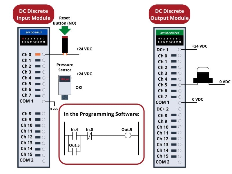
To further illuminate these fundamental concepts, we will examine the operation of a simple PLC system designed to energize a warning beacon in the event that a fluid process line experiences a low pressure. The PLC’s task is to energize a warning lamp if the process vessel pressure ever falls below 270 PSI and keep that warning lamp energized even if the pressure again exceeds the trip point of 270 PSI. This way, operators will be alerted to both past and present process vessel overpressure events.
DC control voltage (+24 and 0 volts) provides electrical energy for the signal potential for the input switches and power for the warning lamp. Two switches connect to the input of this PLC: one normally-open pushbutton switch acting as the alarm reset (pressing this switch “unlatches” the alarm lamp) and one normally-open pressure switch acting as the sensing element for the process pressure:
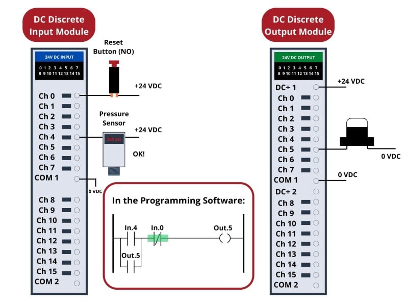
The reset pushbutton connects to discrete input channel 0 of the PLC, while the pressure switch connects to discrete input channel 4. The warning lamp connects to discrete output channel 5. Indicator LEDs next to each I/O terminal and at the top of each module visually indicate the electrical status of the I/O points, while green-shaded highlighting shows the virtual power status of the “contacts” and “coils” in the PLC’s program, displayed on the screen of a personal computer connected to the PLC through a programming cable.
With no one pressing the reset pushbutton, that switch will be in its normal status, which for a “normally-open” switch is open. Likewise with the pressure switch: with process pressure sufficiently higher than the trip point of 270 PSI, the pressure switch will also be in its normal status, which for a “normally-open” switch is open. Since neither switch is conducting electricity right now, neither discrete input channel 0 nor channel 4 will be energized. This means the “virtual” contacts inside the PLC program will likewise be in their own normal states. Thus, any virtual contact drawn as a normally-open will be open (not passing virtual power), and any virtual contact drawn as a normally-closed (a diagonal slash mark through the contact symbol) will be closed. This is why the two normally-open virtual contacts In.4 and Out.5 have no highlighting, but the normally-closed virtual contact In.0 does – remember, the colored highlighting represents the ability to pass virtual logical power, NOT an indicator of the actual current flow through the switch.
If the process vessel experiences a low pressure (\(<\) 270 PSI), the pressure switch will actuate, closing its normally-open contact. This will energize input channel 4 on the PLC, which will “close” the virtual contact In.4 in the ladder program. This sends virtual power to the virtual “coil” Out.5, which in turn latches itself on through virtual contact Out.5 and also energizes the real discrete output channel 5 to energize the warning lamp:

If now the process pressure goes back above below 270 PSI, the pressure switch will return to its normal state (open), thus de-energizing discrete input channel 4 on the PLC. Because of the latching contact Out.5 in the PLC’s program, however, output channel 5 remains on to keep the warning lamp in its energized state:

Thus, the Out.5 contact performs a seal-in function to keep the channel 5 output bit set (1) even after the low-pressure condition clears. This is precisely the same concept as the “seal-in” auxiliary contact on a hard-wired motor starter circuit, where the electromechanical contactor keeps itself energized after the “Start” pushbutton switch has been released.
The only way for a human operator to re-set the warning lamp is to press the pushbutton. This will have the effect of energizing input channel 0 on the PLC, thus opening virtual contact In.0 (normally-closed) in the program, thus interrupting virtual power to the virtual coil Out.5, thus powering down the warning lamp and un-latching virtual power in the program:
REVIEW:
-
Bits are a single piece of on/off information, commonly used for digital input and output devices. They can have a value of 1 or 0 only.
-
Contact instructions monitor input information, while coils command the outputs to energize.
-
When a rung of a ladder program has a path of ‘closed’ logic from left to right, the output coil will energize. If the logic path is broken, much like a circuit, the coil will de-energize.
Interested in more PLC content?
Related Videos:
Textbook Pages:
Tutorials and Technical Articles:
- Ladder Logic in Programmable Logic Controllers (PLCs)
- Intro to PLC Programming with Rockwell’s Studio 5000 and CompactLogix
- Intro to Siemens S7-1200 PLC and TIA Portal Programming
- Understanding PLC Program Commands: Timers
