We have MARKVIES system installed in our ST. One of its card 1D2B card became faulty during unit operation.

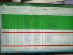
On 30th June 2024, unit was running on part load. Below diagnostic alarms occurred followed by all Turbine Radial and Thrust Bearing temperature TX became bad i.e. the signal quality turned bad state. Below is the alarm Log extracted from MARKVI:
1720090775487.png

It is quite evident from the first diagnostic alarm “Pack internal reference voltage out of limit” i.e. there was some issue in the supply of card. Anyhow, INST cut off the communication and replaced the faulty card. The bad signals became healthy after card replacement.
Instability in the power supply can cause the internal reference voltage to fluctuate. Trends of UPS system as well as DC system checked/analyzed, but no significant change observed.

Previously we have faced similar events of Card failure. Anyone can suggest the failure root cause of these cards in MARKVIE?

Thanks in advance.
Regards
Muhammad Bilal
 
@blalmoin,

The designers of the Mark* VIe/VIeS were a little overconfident in the ability of the I/O Packs to withstand heat. Arranging them in a vertical column causes the heat from lower I/O Packs to rise up directly to I/O Packs in the column above them. Some I/O Packs generate more heat than others. But, heat is an enemy of all electronics. Mark* VIe/VIeS control panels were only cooled by convection (i.e., no forced air circulation), and some of these panels had/have filters on the doors which actually impede natural air flow--particularly if not kept clean.

Age, heat, dust and humidity are big contributors to electronic failures. Proper housekeeping (removing/preventing dust from entering a control panel) is very important. Many people think the purpose of air conditioning (cooling) in a control room is to make it comfortable for humans, or simply to cool electronics. It's not for the first purpose listed, and it's only marginally for the second purpose; the primary purpose is to reduce humidity in the control room. Keeping a control room excessively cold can cause any humidity that gets into the control room to condense--which is NOT good. Keeping a control room excessively cold in a humid ambient environment can actually draw humidity/moisture into the area. MANY control rooms/panels have open floors where control cables pass from the outside the area into the control panels. And, if not properly sealed (sometimes that is not easy to do because of the practices/methods used during the construction of the control area) that can lead to humidity/moisture being "drawn" into the control panels, where it can condense. Mixed with dust and contaminants that can lead to the premature failure of electronics.

Occasionally a manufacturer will receive a shipment of components which don't always meet specifications that get used in the manufacture of electronic assemblies. The OEM used to provide what were called TILs (Technical Information Letters) to people operating the equipment to alert them to possible problems with certain equipment which might contain suspect components. Have you consulted the OEM's TILs on this matter?

Just as a matter of clarification the designation you listed (1D2B) refers to a physical location not an actual I/O Pack. I/O Packs usually have a four-character designation which refers to the functionality of the I/O Pack; for example PDIO, or PRPA.

But, if your only interest is in trying to blame the manufacturer for poor electronic assembly quality, it's more likely installation conditions that are contributing to a high failure rate. But, again, if the I/O Packs are arranged in vertical columns AND air flow in the control panel is low or somehow blocked. The packager of the control panel could be responsible for incorrectly stacking I/O Packs in vertical rows, but the solution for that is relatively simple: improve air flow (while maintaining cleanliness!).

Finally, the photo you provided is unclear and difficult to read. I tried looking at it with a 27-inch monitor, but it's still blurry and trying to zoom in on areas just made the image more difficult to read.
 
@blalmoin,

The great thing about public forums on the World Wide Web is that MANY people can read and follow a single thread and learn and understand what is being discussed.

Taking any discussion offline deprives many others of the benefit of learning and understanding.

I have offered the benefit of my experience based on the information provided and have nothing further to offer based on the information provided. If you have further information to offer, please add it to this thread. My experience is that when people don’t provide complete details they are specifically looking for validation of their assessment of the situation and don’t want to consider other possibilities.

If you don’t like my comments/suggestions the ONLY other suggestion I can offer is to investigate the wiring installation to ENSURE the T/C wiring is properly isolated and shielded from high voltage/high current cables and or wiring. At a MINIMUM the high-level cables (greater than 24 VDC) should be isolated in separate cable trays/conduits/vaults as per standard industrial wiring practices. Further, if you T/C extension wiring uses multi-conductor cables, the cables should be shielded as per standard industrial wiring practices (the shield drain wire should be grounded AT ONE END ONLY).

And that’s that. Based on the information provided. If you’re looking for validation of some other cause (real or perceived) you haven’t provided enough evidence/proof/information.

I’m certain if you share any new information/evidence/poof someone else can offer more assistance.

Blessed day.
 
Top