Ladder Diagram for Motors Control - Need Help With Limit Switches

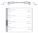
I'm developing my first PLC Ladder Diagram to control two motors(left & right) that turn screw jacks that move from a stowed position, to a deployed position - see attached. The DC motors are reversible, to rotate the screws from stowed to deployed, and back. There are four limit switches (stow left & right, deploy left & right). Plus, there are two momentary switches - one for deploying (AKA Open), one for stowing (AKA Close).

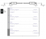
I have an Arduino OPTA PLC, and have programmed it using the LD shown in the attachment. The LD drives the motors correctly, except at the transition between fully deployed, and stowing, and then from fully stowed to deploying. I don't know how to make the LD come off of the limit switches, to get going. Currently, my Stow limit switches are NO, and the Deploy limit switches are NC - but I can changed them, if needed.

I'd appreciate some help figuring this out. I'm using the ArduinoPLC IDE, and can share any files needed to replicate my work.

Thanks,
Bobmotors_and_limit_switches_diagram.png
 
I would make the limits Close on actuation. I would program a NO contact from the motor drive coil in parallel with the a NO contact from the PB. This parallel combo would be in series with a NC from the limit at the end of the drive. This series/parallel combo would be what picks up the drive coil.

Basically
C = (A or C) and B
where A= NO momentary Deploy button
B= NC fully deployed limit switch
C= motor deploy drive coil

When you push the deploy button (A) the output will latch on via the "seal in" contact from (C). It will run the motor until the limit switch at the fully deployed position closes which breaks the seal in via the (B) contact.

Follow similar logic for the other drive actions.

Hope this helps
Thanks very much, MWO! I've attached my changes based on your suggestions, and it's working fine. I now understand how "seal in" works.

Bob
 

Attachments

Something you might want to think about is how is the motor stopped if the limit switch fails. What if one side stops mid travel and the other keeps going. Just some things to think about when designing a circuit. Have fun.
 
While testing the hardware, I found that the motors keep running when the momentary switches are released. I need them to quit working when released. So I changed the "seal in" coils to Positive, which seems to work - see attached. What do you think? NOTE: The Momentary switch is a keyed switch (Dead Man), it can only be either Open or Close - I added it to the attachment.

Oh, yeah, thanks for reminding me about testing a limit failure! What I've done to simulate a limit failure, in my hardware, I put the limits in Stowed state, press & hold Momentary_Open, close Left_Deploy_Limit, then close one of the Stow_Limits. Tried both Stow_Limits. Tried other variations of setting Limits SWs, all seems to work - appropriate LEDs and Motors react correctly. But, is there something I should add to the LD to make sure this is correctly handled?
 

Attachments

I guess I’m not familiar with the term “POSITIVE” coil verses the seal in. I usually see the P as a pulse contact which closes for 1 scan of the LD If you only want the motor to run while you are holding the switch, I don’t see where any parallel contact would be needed.

My concern with the seal in arrangement was if the limit failed, there would be no stopping the motor. I was thinking you might want to limit the time of the seal in would latch. If the device took 5 seconds to deploy, you could have a timer running that would cancel the seal in after 5.5 seconds. Since you are doing it without a seal in contact you don’t need to worry about that.

As far as other limit failure tests, I offer this suggestion. If you cut the wire to the limit switch how will it operate. In your case, I thing the circuit would still operate but not automatically stop at the end of the stroke. If you reverse the contact sense of the limit then it wouldn’t function at all and you would not be depending on a limit switch that will not work. You have to decide which is the better failure mode.

Good luck and have fun.
 
Thanks @MWO, that timing technique seems like good advice. I will look into it. Right now, the PLC (Finder OPTA) is failing me, so I'm looking for a replacement. Will be posting, asking for suggestions.
 
Top