GE Frame 9E (Mark VIe) – Loss of Flame Trips Above 105 MW: FSRN/FSRT Crossover

GE Frame 9E (Mark VIe) – Loss of Flame Trips Above 105 MW: FSRN/FSRT Crossover

Hello everyone,


I would appreciate technical advice from engineers experienced with GE Frame 9E gas turbines and Mark VIe control systems.


We are experiencing a recurring Loss of Flame trip on our GE Frame 9E gas turbine (GT#01) at high load, generally above 105 MW, and I am trying to identify the root cause before making any control-logic or combustion-tuning changes.

1. Turbine and control system

  • Turbine: GE Frame 9E
  • Control system: GE Mark VIe
  • Generator rated output: approximately 150 MVA
  • Normal operating load: up to approximately 110 MW
  • The problem occurs primarily above 105 MW, particularly around 109–111 MW.
2. Observed FSR behavior before the trip

During high-load operation, we observed that FSR repeatedly shifts between FSRN and FSRT. Just before the trip, FSRT remains active for approximately two minutes, after which the turbine trips on Loss of Flame.


Our signal identification is as follows:


  • SPD = FSRN
  • TEMP = FSRT

The FSRT and FSRN values are currently much closer than they were historically at comparable loads. The FSR reference changes between these two signals, and FSRN can suddenly decrease below the previously active reference.


I am investigating whether the reduction in FSRT and the resulting fuel-reference transfer are contributing to the loss of flame.

3. FSRT calculation and increased TTXM

The FSRT calculation in our control logic is understood to be:


FSRT = (TTRXB − TTXM) × 0.2 + FSR


TTXM is derived from the corrected readings of 24 exhaust thermocouples, using a median/representative temperature calculation.


Historical and current operating data at approximately 110 MW show the following:


  • Historical TTXM: approximately 1044°F
  • Current TTXM: approximately 1072°F
  • Increase: approximately 28°F

If TTRXB and the other terms remain unchanged, a 28°F increase in TTXM would reduce the calculated FSRT by approximately 5.6 FSR units.


My current hypothesis is that the increased TTXM is reducing FSRT until it falls below FSRN, causing the fuel reference to transfer to the lower value. Could this sequence contribute to a Loss of Flame trip?


I would also appreciate advice on whether this TTXM increase is more likely to indicate a genuine increase in exhaust temperature, a thermocouple measurement issue, or a combination of factors.

4. Fuel gas supply conditions have changed

The plant was shut down for approximately four years following a major incident. During the previous operating period, the fuel gas supply arrangement was:


  • Gas available from a nearby gas supply source at approximately 55 bar.
  • The first pressure-reduction stage reduced the pressure to approximately 24 bar.
  • A second stage reduced it to approximately 5.5 bar, and a gas booster compressor was used to provide the required GT supply pressure.
  • The gas booster compressor delivered fuel gas to the turbine at approximately 24 bar and 60°C.

Following a change in the applicable regulatory conditions, we are now bypassing the second pressure-reduction stage and the gas booster compressor. The turbine is supplied with gas at approximately 24 bar and 25°C.


Therefore, the fuel gas supply temperature has decreased by approximately 35°C, while the nominal pressure supplied to the turbine remains approximately the same.


Could this change in fuel gas temperature, density, metering characteristics, or fuel-control compensation affect actual fuel mass flow, combustion behavior, exhaust temperature, or DLN combustion stability at high load?


We have not yet established that this fuel-gas change is responsible for the problem, but it is an important difference between the historical and current operating conditions.

5. Four-year shutdown and exhaust thermocouple condition

The turbine remained shut down for approximately four years. The exhaust thermocouple terminal boxes are exposed to outdoor weather, and no specific terminal-box maintenance or inspection was carried out before recommissioning.


Could moisture ingress, corrosion, degraded connections, or other thermocouple-circuit problems cause a systematic positive temperature bias in TTXM?


Since TTXM is calculated from 24 corrected thermocouple readings, I would appreciate advice on how to distinguish a genuine overall exhaust-temperature increase from measurement-chain errors.

6. IGV behavior

We have also observed an IGV-related issue during high-load operation, including an event in which the IGV appeared to move toward fully open in preselect load mode.


Could a change in airflow, IGV scheduling, compressor performance, or the fuel-to-air ratio be related to the increased TTXM and the Loss of Flame trips above 105 MW?


I have not yet established a direct causal relationship between the IGV behavior and the FSR problem.

7. Questions for the community

I would particularly appreciate advice on the following:


  1. FSR/FSRT logic: Could increased TTXM cause FSRT to fall below FSRN and lead to a fuel-reference transfer that contributes to Loss of Flame? What other signals should be examined to establish the actual trip sequence?
  2. Fuel gas temperature: Could changing the fuel gas supply temperature from 60°C to 25°C at approximately 24 bar materially affect actual fuel mass flow or DLN combustion stability, depending on the fuel-metering arrangement and temperature compensation?
  3. DLN tuning: After this change in fuel-gas supply conditions, which fuel-metering calibrations, fuel-split schedules, DLN staging parameters, or combustion-tuning checks should be reviewed against the original OEM commissioning data?
  4. Exhaust thermocouples: What tests would you recommend to determine whether the 28°F increase in TTXM is genuine or caused by thermocouple, terminal-box, wiring, or signal-processing errors?
  5. IGV and airflow: Could the observed IGV behavior contribute to the high-load exhaust-temperature increase or flame instability?
  6. TTRXB and FSRT margin: What engineering checks should be completed before considering any change to the TTRXB calculation or related control constants? I want to avoid masking the underlying cause by modifying a control reference.
8. Current approach

Before changing FSR-related constants, DLN schedules, IGV schedules, or TTRXB, I intend to compare historical and current operating data at the same load and verify the exhaust-temperature measurement chain, fuel-gas characteristics, actual fuel flow, and relevant Mark VIe control signals.


I would be grateful for any practical troubleshooting experience, particularly from engineers who have worked on GE Frame 9E DLN turbines with Mark VIe controls.


Thank you in advance for your help and suggestions.
 
@safiquebpdb,

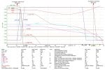
Thank you for posting the Trend data. i only have a few minutes to write this initial response. I do wonder why you posted data for such a short time frame--less than one second. I have a high suspicion that this is all interpolated data because the scan rate for this trend was longer than one second.

You made a very serious omission when you didn't clearly state at the very top of the original post the machine uses DLN-I combustors.

You are grasping at straws--and a lot of them.

You need to understand the dewpoint of the natural gas as it is now versus what it was before the four year outage. Every time natural gas passes through any kind of flow restriction (including filters and/or coalescers, control valves, and nozzle orifices there is a temperature decrease and that can lead to condensation of entrained natural gas vapors into liquids which can affect the combustion. Particularly DLN-I combustion.

I think, after only one quick read of your original post, you need to review your description of the fuel gas pressure pre- and post four year outage. Maybe it was just my quick read but it doesn't seem to be a very good description. Is the source of the natural gas the same as before the outage, or has it changed? (It might be coming from natural gas storage tank, but did the natural gas originate at the same source? Have you tested the natural gas to see what it's composition is post outage?

There is no flame indication on the graph. None.

Loss of Flame Trip means that flame was lost (extinguished) BEFORE any other condition which would have resulted in a trip was detected. It can--and does--happen, that flame is lost before any other trip condition was detected that would have resulted in a trip (sudden shut-of of fuel).

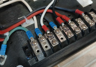
T/C wiring is something of a sensitive thing. It would behoove you to inspect every termination in every junction box for all 24 T/Cs. FOLLOW STANDARD THERMOCOUPLE TERMINATION PRACTICES--WHICH MEANS YOU CAN'T JUST LAND WIRES AT A TERMINAL BOARD WILLY-NILLY. THIS HAS BEEN DOCUMENTED MANY TIMES BEFORE ON CONTROL.COM. I don't think this is a large part of the issue(s) here, but it certainly could be if the outside JBs were properly closed or inspected before the re-commissioning.

That's all I have time for now. Please explain the fuel gas situation better, and the Trend recorder time situation.
 
@safiquebpdb,

Lots of thoughts here. First, the turbine control system was most likely programmed by GE Belfort, which means it likely doesn't follow long-established control philosophies and principles for GE heavy duty gas turbines--in many respects. Sorry; but that's just life with GE equipment from Belfort. And without being able to see the application code running in the Mark* VIe we would be making a lot of guesses (and I, in particular, loathe and despise guessing about these types of things--so I won't. Guess.) The FSRT calculation you listed doesn't look like anything I've every seen before (in more than 40 years of working on GE-design heavy duty gas turbines--but then this is a GE Belfort machine, so that may explain a lot).

You mentioned this is GT #01. Are there other machines on the site which aren't experiencing issues?

If the site is using Pre-selected Load Control to operate the machine, well, that's not really a proper way to operate GE-design heavy duty gas turbines. If you want the machine to operate at Base Load, click on the BASE LOAD load button and let the machine do it's thing. If you want to control to a particular load setpoint using Pre-Selected Load Control and that setpoint is very near the FSRN/FSRT transition point, DON'T. Choose another load either a couple of MW lower or just choose Base Load and live with the difference. Base Load means the IGVs should be at maximum operating angle and the actual exhaust temperature (TTXM) should be equal to the calculated exhaust temperature control reference (TTRX)--that's what the Mark* does when Base Load is selected--puts as much fuel into the machine as possible to keep TTXM as nearly equal to TTRX as possible without going over TTRX. And the resulting load will be what it will be for the current ambient and machine conditions. Period. Full stop. If that load is slightly more than some desired load setpoint, so be it. And if it's less than some desired load setpoint, then the machine ain't gonna make that load. Not on Pre-Selected Load Control or Base Load. [NOTE: If the machine has Peak Load, well that's another issue.]

The transition between FSRN and FSRT is intended to be smooth and bumpless. Now, if someone has been mucking with Control Constants (NOT recommended unless one understands ALL of the knock-on effects) then the transition can be rough and difficult.

DLN-I machines use IGV Exhaust Temperature Control below Base Load because they do (lots of reasons, but they want to keep the internal combustor firing temperature as high as possible for stable combustion). So usually, the IGVs are throttled a little bit (kept closed) to reduce the air flow to make the firing temperature hotter. UNTIL the machine gets close to Base Load, when the IGVs will be at maximum operating angle, because that is one of the prerequisites for Base Load operation.

Thermocouple wiring is not "simple". Well, it is actually, because there are only two connections (Chromel and Alumel) BUT the terminations between Chromel wires and Alumel wires must be done in a certain way or there will be errors introduced into the circuit based on the ambient temperature in the junction box where the terminations are made. Some people think and insist that special Chromel and Alumel terminals MUST be used for connecting thermocouples to thermocouple extension wire--but that's not true. HOWEVER, when not using Chromel/Alumel terminal boards the terminations between Alumel wires and Chromel wires ?>>>MUST<<< be done is specific manner for BOTH the Chromel and Alumel terminations of a thermocouple circuit.

If the exhaust T/C junction boxes weren't assembled properly (conduit/wire penetrations through the top of the junction box, for example) or the doors weren't properly closed during the four year outage then it's entirely possible there might be some issue with the terminations due to moisture ingress. We can't help with that. But it is possible to use an analog T/C simulator to "inject" simulated temperatures from the exhaust junctions boxes and view the results on the HMI using ToolboxST. (Removing the 24 T/Cs to put them in a controlled temperature bath would be ... not fun.) But, it should be possible to review the as-found condition of the external exhaust T/C junction box terminations to determine if they were done properly to begin with and what the present condition is and what needs to be one to get the terminations to a industry standard and proper condition.

Was an off-line water wash performed prior to the re-commissioning?

What are the conditions of the turbine inlet air filters post-outage and prior to re-commissioning?

We don't know anything about the site where the machine is located. Is it in an arid area? A humid area? An area that experience large temperature ranges? An area with airborn dust and or air contaminants, such as from a nearby refinery or cement plant or chemical plant, or a busy road/highway with lot of diesel truck (lorry) traffic?

It would be helpful if you could list all the alarms that were active prior to the trips (Process- and Diagnostic Alarms).

But, before you make any changes to the pre-outage schedules you mentioned I would be asking GE for help with this problem. Specifically the gas temperature/pressure situation AND the TTXM discrepancy.

And, while Trends are extremely helpful--we need Trends that show actual data, not just the lines connecting actual data points. If the period of the Trend capture you provided (which was very nicely notated!!!) was more than 1 second between actual data points (usually shown on Trends with triangles or diamonds when viewed at higher resolutions).

It would also be helpful to know what the machine speed was doing during these trips. Was it stable? Was it varying?
 
@WTF?
Thank you for your valuable replies, please forgive me for late response.

  • 1) I analyzed the entire trend and took a screenshot zoomed in on only the portion corresponding to the moment of the trip. To make it easier for everyone to understand, I labeled each parameter code beside its corresponding plot using the same color. I have the complete trend and can send it to you by email or WhatsApp if you wish.
  • 2) The fuel source has not changed; only the gas booster and the second run of the RMS have been bypassed. There is no buffer or storage tank in our fuel system.
  • 3) However, at the time of the trip, the GT was operating at 105 MW. As FSRN decreased and crossed below FSRT, FSR naturally began to follow FSRN. When FSRN dropped sharply to zero, FSR also went to zero. The control valves consequently closed, extinguishing the flame, and the GT tripped with a “Loss of Flame Trip” alarm. Since the “Loss of Flame Trip” was a consequence of the decrease in FSR, the flame intensity traces have been hidden to reduce visual clutter in the graph.
  • 4) The doors of the TC TBs are securely closed, but they cannot be opened for inspection while the plant is running.
  • 5) Our logic diagram provides a general outline of the FSRT calculation. I have attached an image of the logic block and its help file.
FSRT Logic Block.jpeg

  • 6) We have two GTs at our plant. HGPI was carried out on GT #01 in November 2021 and on GT #02 in December 2021. On May 29, 2022, the power plant shut down following an accident. GT #01 had already been temporarily shut down due to a gas shortage for two days before the accident, while GT #02 was operating in simple-cycle mode. The accident severely damaged GT #02’s unit breaker, unit transformer, auxiliary transformer, the control, protection, and auxiliary power wiring of the plant’s 230 kV substation, and the 6.6 kV bus. After various administrative complications were resolved and rehabilitation work was completed, GT #01 was restarted in February 2026. Rehabilitation work on GT #02 is ongoing, with a deadline of April 2027 for its return to operation. Since GT #01 was restarted, it used to trip on “Loss of Flame” at a load of 110 MW; the same trip now occurs at 105 MW.
  • 7) The GT is operated in preselect mode in accordance with the requirements of the National Load Dispatch Center. However, if it can be confirmed that it will not trip at base load, it can be operated in base-load mode, subject to approval from the National Load Dispatch Center.
  • 8) Before restarting, the filters were replaced and an offline water wash was performed.
  • 9) The filters were almost new before the plant shut down, and they were replaced before restarting.
  • 10) The site is in a typical rural area [Google Map Location: https://maps.app.goo.gl/cL4WaU2Kc3oyn96bA ] There are no chemical or cement or refinery industries nearby, but there is a ceramic factory and a highway with moderate traffic consisting of vehicles running on octane gasoline, petrol, and diesel.
  • 11) At the time of the trip, the GT speed was normal and stable.
  • 12) Alarm Screenshot during “Loss of Flame Trip” attached for you.Loss Of Flame Trip.jpeg
 
@safiquebpdb,

1) Trender (or Trend Recorder) doesn’t record data at rates that an analog chart recorder would—though it draws lines as if it does. Again, at “higher” resolutions you will see diamonds or triangles that reflect actual recorded data for each parameter appearing on the display. (Presuming all the data is being collected at the same rate there will be vertical “columns” of diamonds or triangles at the time the actual data was recorded.) The lines for each parameter appearing on a display BETWEEN diamonds/triangles are interpolated—not actual data. (By the way, your notations on the graph were extremely helpful without ToolboxST!)

2) Noted.

3) The fact that FSRN is decreasing when actual machine speed is stable is extremely important to understand. Droop Speed Control operates on the error between machine speed reference and machine actual speed—so, if machine actual speed (TNH) is NOT changing that implies the machine speed reference IS changing.

Here’s where the GE Belfort connection becomes important. It’s entirely possible GE Belfort is performing Droop Speed Control with their own home-brewed Droop Speed Control method, rather that using tried-and-proven GE Constant Settable Droop, which is what GE has historically used with DLN combustion. SO, without being able to see the application code running in the Mark* VIe at the power station it’s nearly impossible to understand precisely what is causing TNR to change to cause FSRN to decrease when TNH is stable.

In a typical Droop Speed Control algorithm (either “straight” Droop Speed Control or Constant Settable Droop Speed Control) when actual machine speed, TNH, is constant (which it should be when synchronized to a stable grid) FSRN will decrease then TNR decreases (because the error is based on (TNR minus TNH) so if TNH is not changing but TNR decreases then FSRN will decrease).

TNR is a function of the operator clicking either on SPEED/LOAD RAISE or SPEED/LOAD LOWER OR on the output of the Pre-Selected Load Control function OR some other automatic load control input to the Mark*—such as AGC (Automatic Governor Control) or some PMS (Power Management System) or some other external (typically) external signal that effectively changes TNR, either by some pulse or some “calibrated” analog signal (4-20 mA, for example).

The above is how Droop Speed Control has historically been accomplished on GE-design heavy duty gas turbines using tried-and-proven philosophies and techniques since the 1950s. That is, until GE Belfort was handed the authority to ignore standard practices and develop their own methods and practices—often without proper testing and oversight and verification. Without being able to see and analyze the application code running in the Mark* and without knowing a lot more about how the plant is operated it’s almost impossible to add any more to this topic (what might be causing TNR to suddenly decrease). I have yet to be able to look at the Alarm Display you attached so there might be something else I can add later.

4) Yeah, I know this method of thinking. Opening a JB of a running turbine might disturb a termination or improperly crimped terminal and result in a machine trip. (Then why isn’t it common practice during maintenance outages to open JBs and check for loose terminations and poor crimps and be proactive so that the JB can be opened when running with much more confidence. Ahh, simply because no one has confidence that the terminations and crimps are good because they’ve never been checked….)

5) I’m going to hold off on commenting on this because you said FSRN decreased below FSRT, or did you mean FSRT increased above FSRN making it appear that FSRN was decreasing??? Because that’s not how I interpreted what you wrote.

6) Noted.

7) Oh, I really don’t want to go there with this line of thought. Look, the typical GE Droop Speed Control method uses the error between TNR (machine speed reference) and TNH (actual machine speed) to increase or decrease FSRN. When the machine is synchronized to a well-regulated grid and the grid frequency is stable (not changing by more than plus-or-minus 0,1 Hz) then the only way FSRN will increase is if TNR increases. (Remember the basic formula is (TNR-TNH).) For FSRN to decrease when the grid frequency (and machine speed) is stable is when TNR decreases.

Pre-Selected Load Control is an automatic method of comparing a load reference to the actual load and adjusting TNR which will result in a change in FSRN. AGC, and PMSs and other external load references will work in exactly the same manner—by changing TNR which changes the error between TNR and TNH and changes FSRN. (By the way when operators are watching the MW meter and clicking on SPEED/LOAD RAISE or -LOWER they almost NEVER know that what they are actually doing is changing TNR to change FSRN to make the MW meter change!)

But since we (I) don’t know what the Droop Speed Control method is in the application code running in the Mark* AND we (I) don’t understand the method the machine is being used to control load it’s impossible for us (me) to say precisely what is happening.

It should be obvious that as long as TNH isn’t changing (which it almost never is on a well-regulated grid) the way to change machine load is to change the machine speed reference. And when nobody or nothing is changing TNR and TNH is stable ((effectively constant at 100,0%) then FSRN isn’t going to change. Full stop. Period. It’s a linear relationship between TNR and FSRN when TNH is stable. Full stop. Period.

8) Noted.

9) Noted.

10) Noted.

11) Then TNH was normal and stable. So that implies FSRN is decreasing because TNR is decreasing (as I understand your description), or …. GE Belfort has struck again.

12) I’ll look at it when I can view it on my computer screen, not on my phone screen.
 
Top