Facebook
 Google
 GitHub
 Linkedin
Networking Tutorial: Connect and Configure a Mitsubishi iQ-F PLC
Learn how to configure the connection for a Mitsubishi FX5UC controller over Ethernet using GX Works 3.
One of Mitsubishi Electric’s flagship PLC product lines is the iQ-F series. The main CPU units include built-in I/O of various types and various footprints to accommodate the quality of I/O. Extension modules are also available to accommodate all kinds of medium machine applications.
The first roadblock in any new PLC adventure is getting the first connection established to download a simple program. After that hurdle, the main goal is to keep practicing to improve skills in learning new functions.
In this article, we’ll walk through the steps required to connect to the PLC using the GX Works3 software.
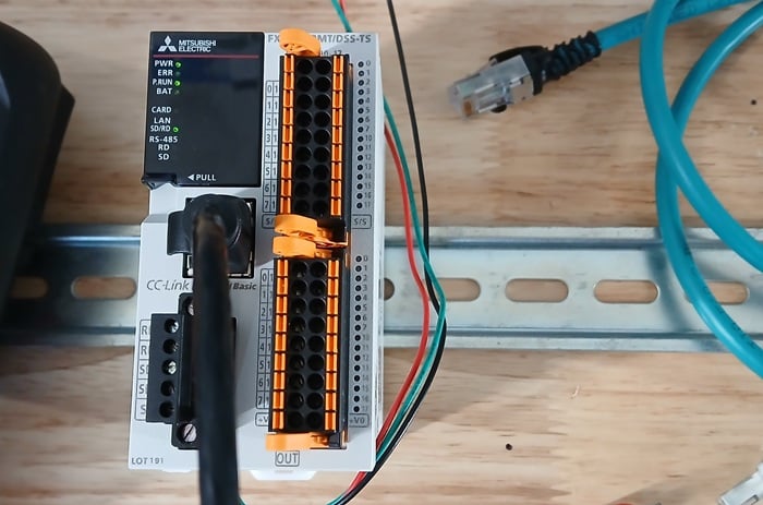
Figure 1. The Mitsubishi FX5UC PLC with built-in I/O.
Required Hardware/Software
You will need a license to use the GX Works3 software, but users can activate a full-capability trial period of the software from the Mitsubishi website.
Our hardware is the FX5UC PLC, a compact form factor with inputs and outputs embedded onto the front. This PLC can only be programmed with an Ethernet connection, so we have two options, and the choice will make a difference later:
- Connect directly from your PC to the PLC with an Ethernet cable.
- Connect both the PC and the PLC to a network switch. It’s fine if there is other equipment connected, perhaps a motor drive, HMI, etc. In my own setup, there are three different PLCs and some other I/O equipment on this same network.
PLC Default Network Config
These PLCs arrive from the factory with an IP address of 192.168.3.250. If your PC (and all the rest of your equipment) is on a different network, you will need to connect to the PLC and change the address.
Go to your PC network settings and change your IP address to the same subnet: 192.168.3.xxx.
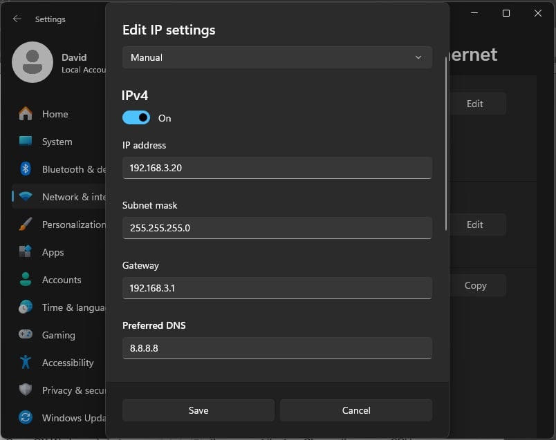
Figure 2. Editing the PC’s IP address in Windows 11.
Starting a New PLC Project
Open GX Works and start a new project from the menu at the top. Choose the proper CPU. Once loaded, the program and configuration tree will be on the left side of the screen.
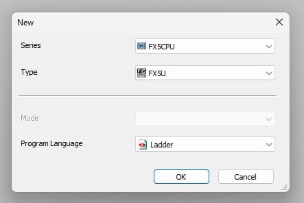
Figure 3. Starting a new project with the correct CPU.
On this left side, expand Parameter -> (CPU type) -> Module Parameter and double-click on Ethernet Port. In this location, we can set our own IP address which will be set into the PLC after a download and restart.
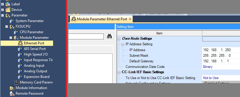
Figure 4. Editing the controller’s IP address.
Note on remote reset: After downloading, you can cycle the power manually, but if you wish to reset the PLC remotely, expand Parameter -> (CPU type) and double-click CPU Parameter. Open the Operation Related Settings, and enable the remote reset option.
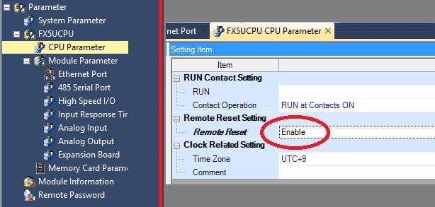
Figure 5. Enabling the remote reset function.
Set the Connection Destination
Now we need to select how the PC is linked to the PLC. From the top menu, select Online -> Current Connection Destination
Now, we need to go back and review those two network topologies that we presented earlier.
- If you connected the PLC to the PC directly via an Ethernet cable, and no network switch is involved, then select Direct Coupled Setting and choose your network adapter from the drop-down menu.
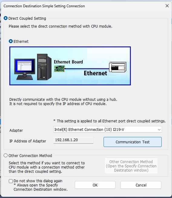
Figure 6. Direct point-to-point com setup.
- If, like me, you are connecting to the PLC through a network switch, then select Other Connection Method, double-click on PLC Module in PLC side I/F, select Connect via Hub, and enter the IP address (at this point, the PLC is still the default 192.168.3.250). Click Find.
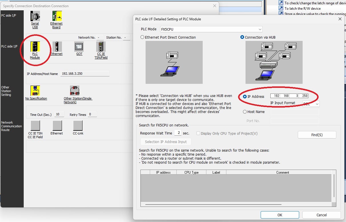
Figure 7. Connection through a switched network.
Download the Configuration
Now that the changes are ready, they need to be downloaded (written) to the PLC. At the top, go to Online -> Write to PLC and select the proper CPU parameters.
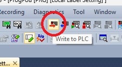
Figure 8. Write to PLC button.
Since we changed the reset setting and provided a new IP address, we must at least select System Parameter / CPU Parameter and Module Parameter. Now Execute, and follow the dialog to download the configuration.
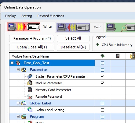
Figure 9. Selecting elements to write to PLC.
Even after the download is complete, the IP address hasn’t really been altered yet. It requires a restart or a reset for that to happen. You can manually power cycle the CPU, but now you can also navigate to Online -> Remote Operations and select Reset.
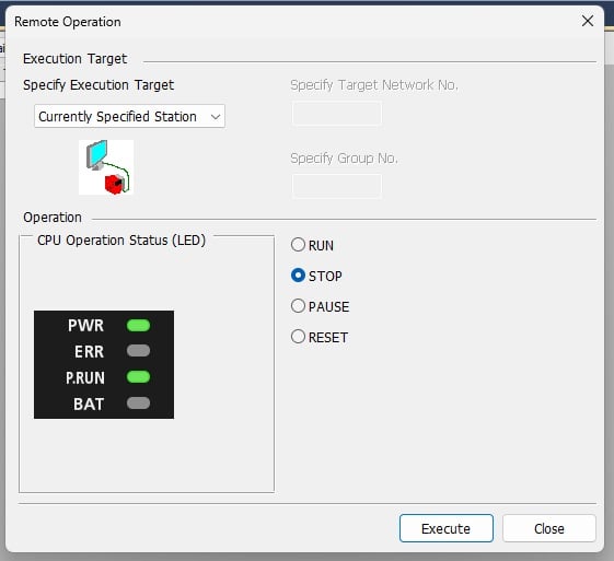
Figure 10. Resetting the PLC remotely.
NOW the IP address has been changed. The only problem is now, of course, your PC is still on the old subnet and the communication line has been broken.
First, change the IP configuration of your PC back to the correct subnet.
Next, return back to the Connection Destination step we discussed earlier, and pick the proper wiring method for your setup, changing the target IP of the PLC if necessary.
To verify, try opening the Write to PLC dialog, and if the communication path is broken, an error message will appear.
Saving Your Work
One last step might be fairly intuitive: save this program to your PC as a template for future programming work. On the other hand, some people prefer to start from scratch each time (for bench testing simple, non-critical programs, of course) to become more familiar with the connection process, and I completely support this idea as well!
Next, we’ll take a look at building a basic program for an iQ-F series PLC, but it follows much of the same ladder pattern as our existing tutorials that use the GX Developer platform already published on Control.com, so be sure to have a look at that series as well.
- Introduction to Mitsubishi PLCs with GX Developer
- Set/Reset Instructions in Mitsubishi PLCs
- Math and Comparison Commands In Mitsubishi PLCs